Adaptive self-calibration method and apparatus

a self-calibration and self-adaptive technology, applied in the field of switching amplifiers, can solve the problems of dramatically increasing the cost of the rest of the system, the requisite accuracy of the feedback component, etc., and achieve the effect of facilitating self-calibration feedback, minimizing or maximizing feedback

Active Publication Date: 2005-03-31
CHARTOLEAUX
View PDF1 Cites 15 Cited by
  • Summary
  • Abstract
  • Description
  • Claims
  • Application Information

AI Technical Summary

Benefits of technology

[0005] The present invention facilitates feedback for self-calibration of any parameter in an analog and/or digital system wherein a system quality factor can be represented by a voltage or current differential. The preferred embodiment is operative to alternately supply two or more optimally equivalent currents or voltages from such a system, detect amplitude and/o

Problems solved by technology

This requisite accuracy of feedback components dramatically increa

Method used


Image

  • Adaptive self-calibration method and apparatus
  • Adaptive self-calibration method and apparatus
  • Adaptive self-calibration method and apparatus

Examples


Embodiment Construction

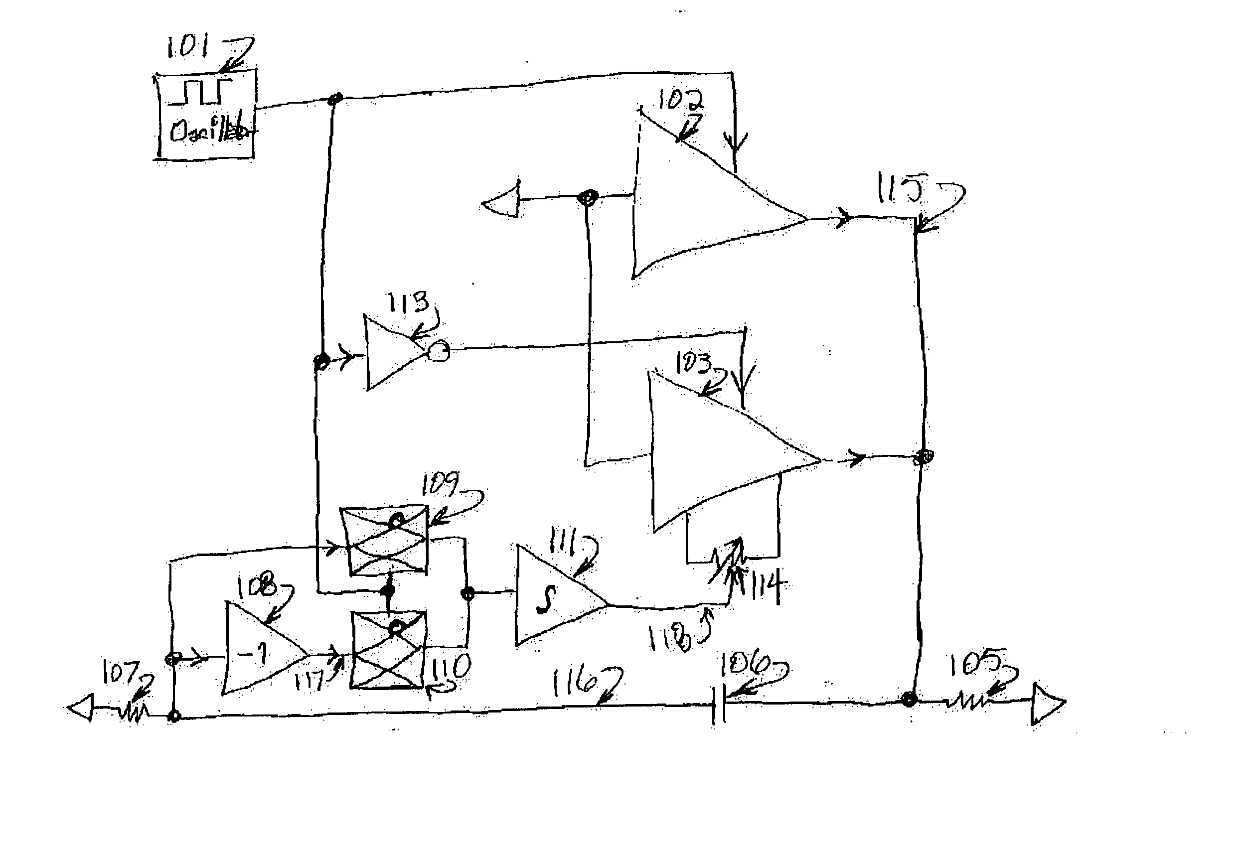
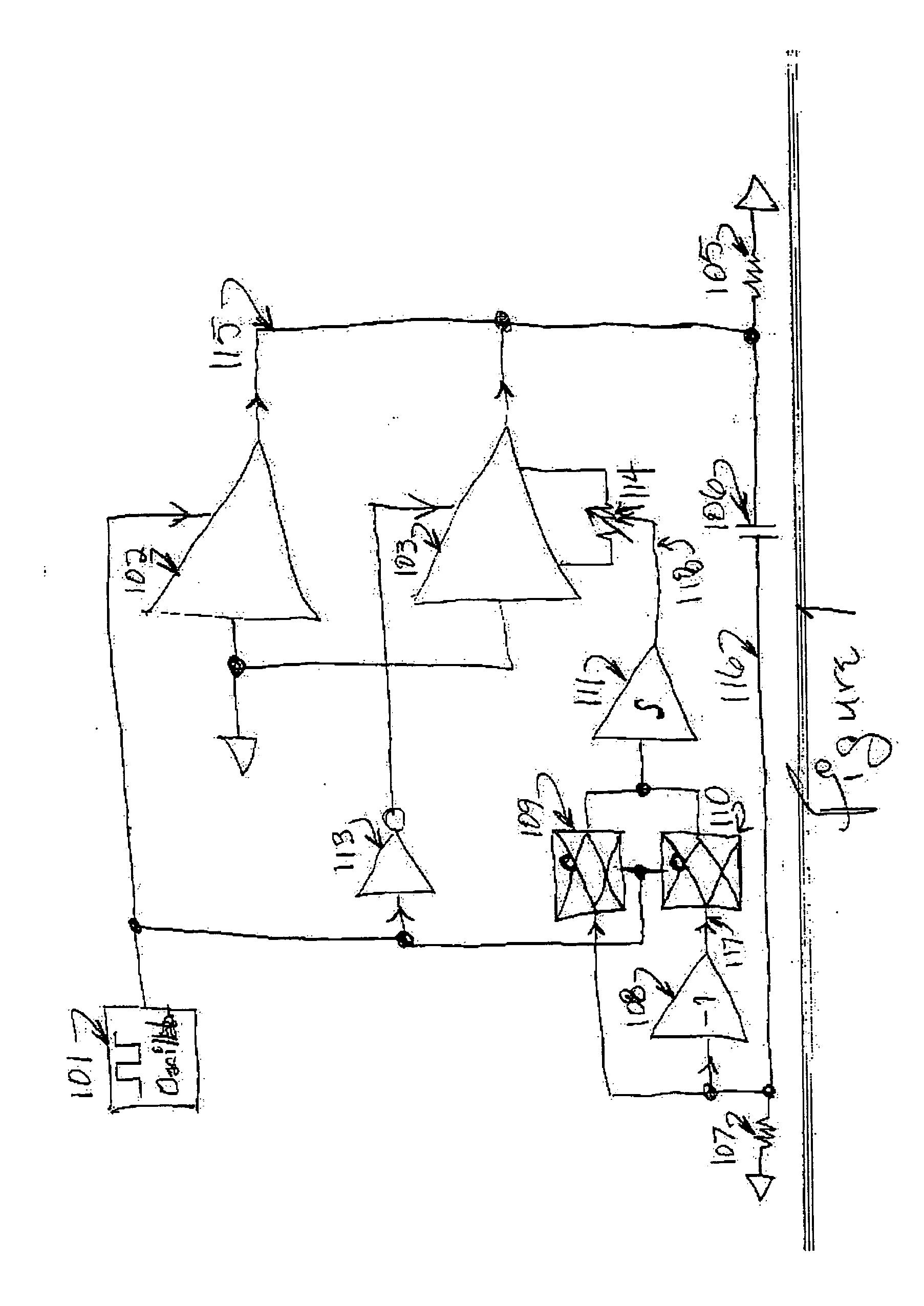
[0008] Referring now to FIG. 1, amplifiers 102 and 103 are shown with associated circuitry operative to null the difference of their offset voltages to zero. Amplifiers 102 and 103 are shown with grounded inputs for simplicity, a condition not otherwise required. The outputs of the amplifiers 102 and 103 are wire-OR connected to load 105, such that one, both, or neither amplifier may drive load 105, under control of individual tri-state enable inputs shown at the top of both amplifiers 102 and 103.

[0009] Square-wave oscillator 101 supplies a control waveform to alternately enable and disable the output of amplifier 102. Inverter 113 inverts the control waveform, thus enabling amplifier 103 when amplifier 102 is disabled, and disabling amplifier 103 when amplifier 102 is enabled. The net effect of the foregoing is that amplifiers 102 and 103 alternately drive load 105 with voltages approaching ground, under control of oscillator 101. Being physical devices, the offset voltages of am...


PUM


Abstract

Feedback for self-calibration of any parameter in an analog and/or digital system is described wherein a system quality factor can be represented by a voltage or current differential. The preferred embodiment is operative to alternately supply two or more optimally equivalent currents or voltages from such a system, detect amplitude and/or phase feedback of resultant output signal at the frequency of the alternation, and use feedback to modify a calibration value, voltage, or current so as to minimize or maximize the feedback, thus effecting self-calibration of the system. Such a method and attendant apparatus enables system self-calibration without need of any high-precision or high-cost components.

Description

REFERENCE TO RELATED APPLICATION [0001] This application claims priority from U.S. Provisional Patent Application Ser. No. 60 / 494,214, filed Aug. 11, 2003, the entire content of which is incorporated herein by reference.FIELD OF THE INVENTION [0002] This invention relates generally to switching amplifiers and, in particular, to methods and apparatus for self-calibration using low-cost feedback components. BACKGROUND OF THE INVENTION [0003] Self-calibration is a cost-effective method of achieving high-accuracy systems using low-accuracy components. In most systems, DC-coupled feedback paths are used to ensure greatest accuracy. However, DC-coupled feedback circuitry must deliver accuracy equal to or higher than that expected of the entire system. This requisite accuracy of feedback components dramatically increases cost, sometimes even above that of the remainder of the system. [0004] A need therefore exists of a feedback method and apparatus for self-calibration wherein low-cost com...

Claims


Application Information

Patent Timeline
IPC IPC(8): H03F1/34H03F3/217H03F3/45
CPCH03F1/34H03F3/45973H03F3/217
Inventor KIRN, LARRY
Owner CHARTOLEAUX
Why Eureka
Try Eureka