Liquid delivering apparatus and method of producing the same

a technology of liquid delivery and apparatus, which is applied in the direction of printing and inking apparatus, etc., can solve the problems of increasing the cost of manufacturing devices, increasing the cost of components in the process of connecting components, and affecting the quality of devices, so as to reduce the number of process steps

Active Publication Date: 2005-03-31
BROTHER KOGYO KK
View PDF9 Cites 16 Cited by
  • Summary
  • Abstract
  • Description
  • Claims
  • Application Information

AI Technical Summary

Benefits of technology

[0012] According to the method described above, the flow-passage-unit forming plates which constitute the at least a portion of the flow-passage unit and the heat-dissipating-member-form...

Problems solved by technology

Where the wiring member such as the FPC or tab terminals is provided between the electrodes formed on the piezoelectric material layer and the external drive circuit as described above, however, the cost of the components and the cost required in a process of connecting the components are increa...

Method used


Image

  • Liquid delivering apparatus and method of producing the same
  • Liquid delivering apparatus and method of producing the same
  • Liquid delivering apparatus and method of producing the same

Examples


first embodiment

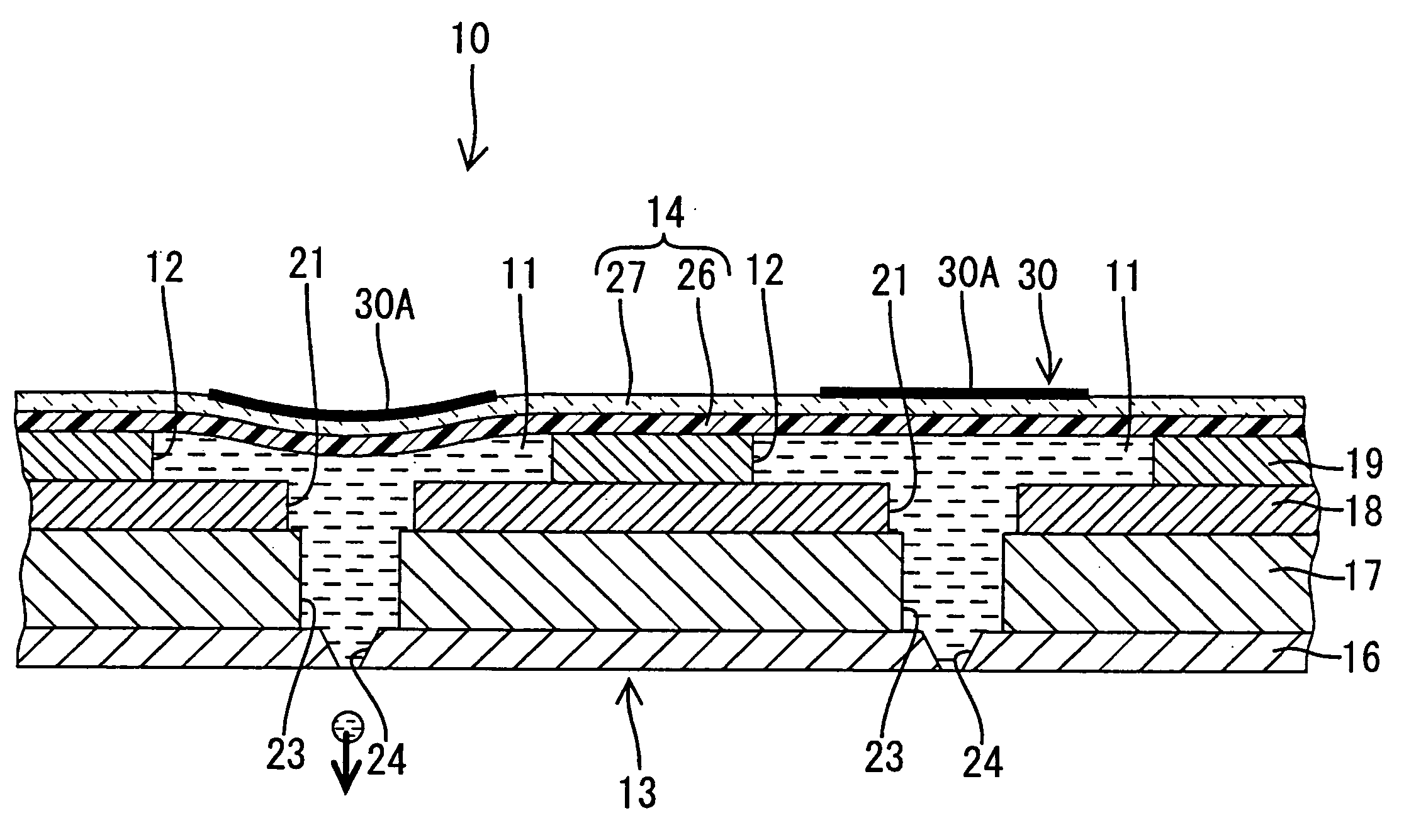
[0042] Next, there will be explained a method of producing the liquid delivering apparatus 10 according to the

[0043] Initially, the piezoelectric material layer 27 is formed on the oscillating plate 26 by (1) an aerosol deposition (AD) method; (2) a piezoelectric-layer forming process or method (sol-gel method); or (3) a bonding process or method.

[0044] Where the piezoelectric material layer 27 is formed by the aerosol deposition method, an aerosol chamber is filled with a piezoelectric material such as fine particles of the lead zirconium titanate (PZT), and the fine particles are agitated or stirred. Subsequently, a carrier gas such as a nitrogen gas or a helium gas is introduced into the aerosol chamber, so that the fine particles are floated in the gas to produce an aerosol. The thus produced aerosol is sprayed at a high speed from a nozzle onto the oscillating plate 26 formed of stainless steel, for instance, and deposited on the surface of the oscillating plate 26 to provide ...

third embodiment

[0069] In the liquid delivering apparatus 50 of this third embodiment, an oscillating plate 52 of an actuator plate 51 is formed of an insulating material such as polyimide synthetic resin. On an upper surface of the oscillating plate 52, there is formed a lower electrode 53. Described in detail, the lower electrode 53 is in the form of a single continuous layer formed at least on a region of the oscillating plate 52 which includes the piezoelectric-material-layer indispensable portions thereof corresponding to the respective pressure chambers 12. The lower electrode 53 is connected, via a connecting portion (not shown) formed on the oscillating plate 52, to the ground of the drive circuit (IC) 100 which is directly mounted on the extending portion 28 (directly as used in this description means in contact with the layer on which mounted as noted earlier). A piezoelectric material layer 54 is formed indirectly on an approximately half area of the upper surface of the oscillating plat...

fourth embodiment

[0092] In the illustrated fourth embodiment, the heat dissipating member 72 is provided in the vicinity of the drive circuit (IC) 100 which is mounted indirectly on the extending portion 63 of the oscillating plate 62 with the insulating adhesive 66 and the insulating layer 64 therebetween, so that the heat generated from the drive circuit (IC) 100 is dissipated from the heat dissipating member 72.

[0093] In the liquid delivering apparatus 60 constructed according to the illustrated fourth embodiment, the insulating member 64 formed of the ceramic material is superposed on the oscillating plate 62 formed of the metal material and the drive circuit (IC) 100 is mounted on the insulating layer 64 via the adhesive 66 while the heat dissipating member 72 is bonded to the above-indicated one of the opposite surfaces of the oscillating plate 62 which is opposite to the above-indicated the other surface thereof on which the drive circuit (IC) 100 is indirectly mounted. According to this arra...


PUM


Abstract

A liquid delivering apparatus, including a flow-passage unit including an opening and a pressure chamber which accommodates liquid and which communicates with the opening; an oscillating plate which partially defines the pressure chamber; a piezoelectric material layer which is one of directly and indirectly stacked on the oscillating plate and which deforms upon application of an electric field thereto so as to oscillate the oscillating plate for delivering the liquid from the pressure chamber through the opening; and an electrode pattern and a drive circuit which apply the electric filed to the piezoelectric material layer. The drive circuit and the electrode pattern are one of directly and indirectly provided on the oscillating plate.

Description

[0001] The present application is based on Japanese Patent Application No. 2003-338124 filed Sep. 29, 2003, and No. 2004-222111 filed Jul. 29, 2004, the contents of which are incorporated herein by reference. BACKGROUND OF THE INVENTION [0002] 1. Field of the Invention [0003] The present invention relates in general to a liquid delivering apparatus and a method of producing the same. In particular, the present invention relates to a liquid delivering apparatus which utilizes a piezoelectric material and a method of producing such an apparatus. [0004] 2. Discussion of Related Art [0005] There is known a liquid delivering apparatus such as an ink-jet recording head, which includes a flow-passage unit in which a plurality of pressure chambers are formed, an oscillating plate which constitutes a part of the wall of each pressure chamber, and a piezoelectric material layer stacked on the oscillating plate so as to oscillate the oscillating plate for permitting liquid in the pressure cham...

Claims


Application Information

Patent Timeline
IPC IPC(8): B41J2/055B41J2/14B41J2/045B41J2/16
CPCB41J2/14233B41J2/161B41J2/1623B41J2/1626B41J2/1631B41J2002/14491B41J2/1642B41J2/1645B41J2/1646B41J2002/14266B41J2/1632B41J2202/08
Inventor SUGAHARA, HIROTO
Owner BROTHER KOGYO KK
Why Eureka
Try Eureka