Thermal response correction system

a correction system and thermal technology, applied in the field of thermal printing, can solve the problems of reducing the density of the output produced by the print head element, and reducing the density of the outpu

Inactive Publication Date: 2005-03-31
TPP TECH LLC
View PDF17 Cites 13 Cited by
  • Summary
  • Abstract
  • Description
  • Claims
  • Application Information

AI Technical Summary

Benefits of technology

It should be appreciated that features of various embodiments of the present invention described above and described in more detail below provide numerous advantages.

Problems solved by technology

One problem with conventional thermal printers results from the fact that their print head elements retain heat after the conclusion of each print head cycle.
This retention of heat can be problematic because, in some thermal printers, the amount of energy that is delivered to a particular print head element during a particular print head cycle is typically calculated based on an assumption that the print head element's temperature at the beginning of the print head cycle is a known fixed temperature.
Further complications are similarly caused by the fact that the current temperature of a particular print head element is influenced not only by its own previous temperatures—referred to herein as its “thermal history”—but by the ambient (room) temperature and the thermal histories of other print head elements in the print head.
This gradual temperature increase results in a corresponding gradual increase in density of the output produced by the print head element, which is perceived as increased darkness in the printed image.
Furthermore, conventional thermal printers typically have difficulty accurately reproducing sharp density gradients between adjacent pixels in both the fast scan and slow scan direction.
This problem results from the amount of time that is required to raise the temperature of the print head element to print the black pixel after printing the white pixel.
More generally, this characteristic of conventional thermal printers results in less than ideal sharpness when printing images having regions of high density gradient.

Method used


Image

  • Thermal response correction system
  • Thermal response correction system
  • Thermal response correction system

Examples


Embodiment Construction

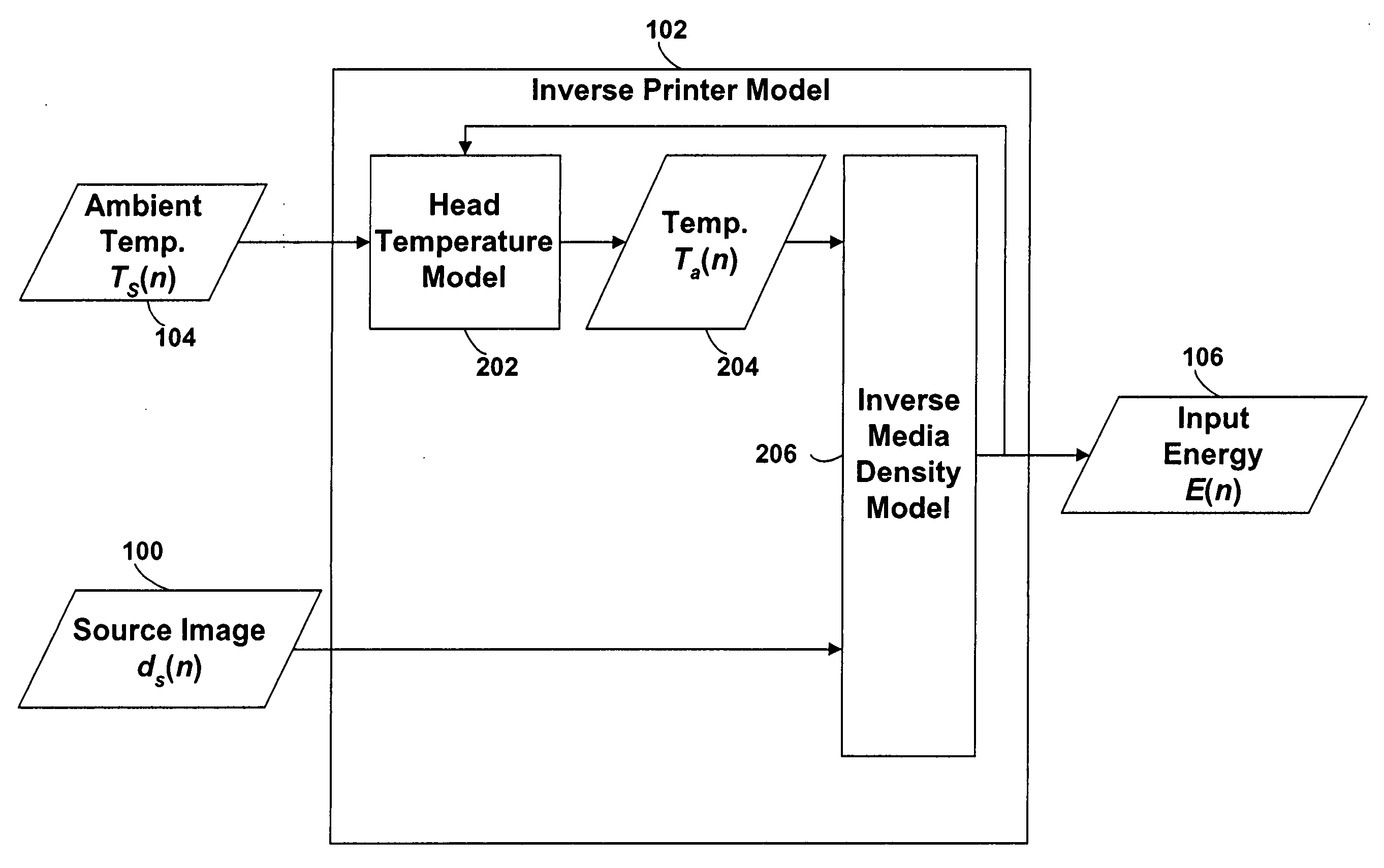
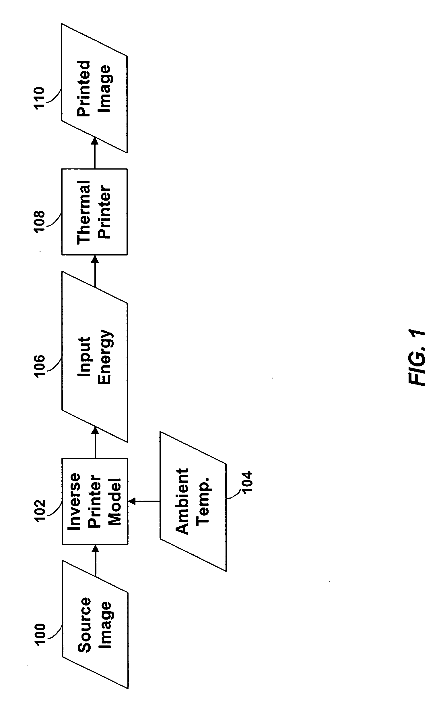
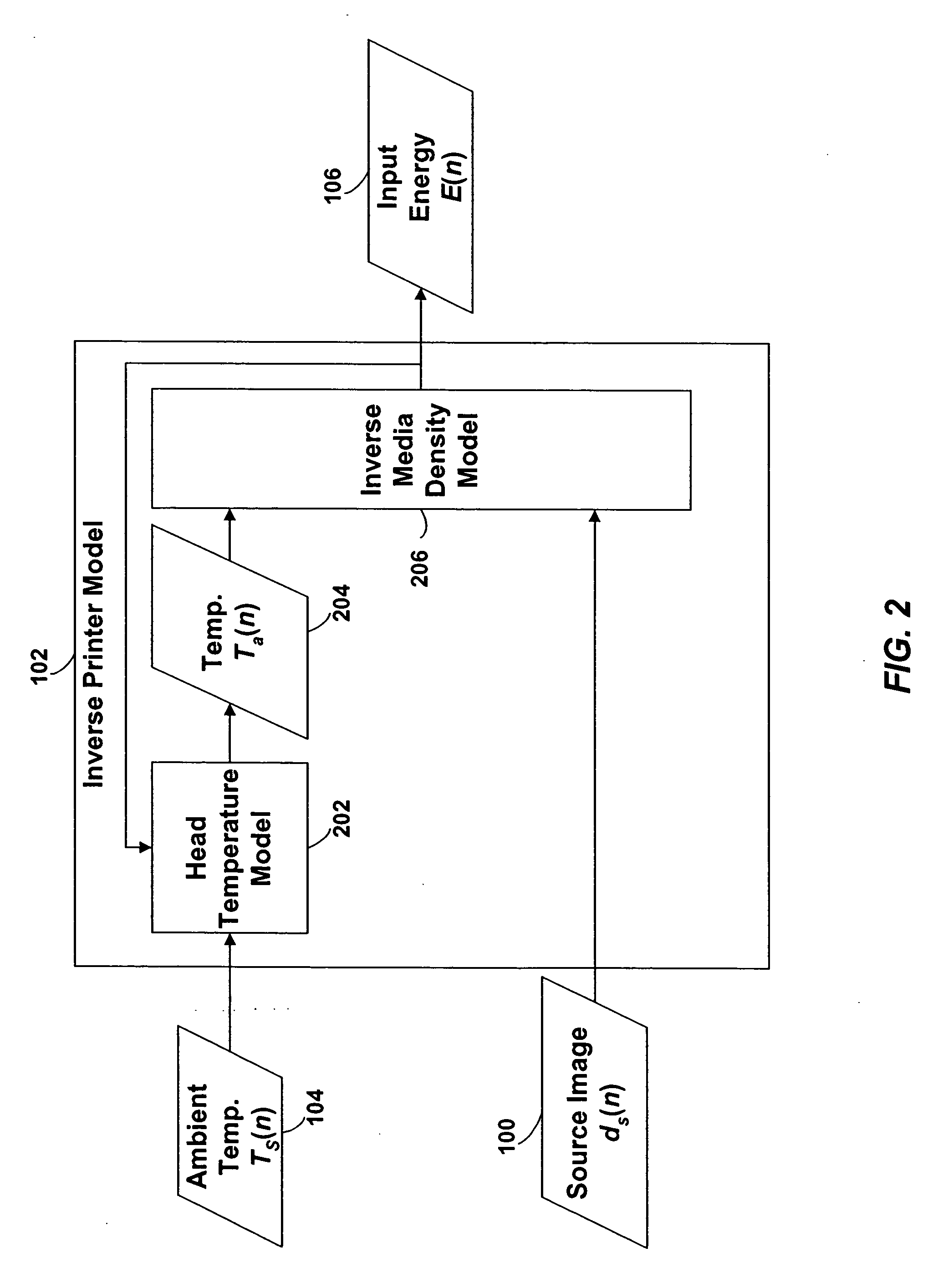
In one aspect of the present invention, a model of a thermal print head is provided that models the thermal response of thermal print head elements to the provision of energy to the print head elements over time. The history of temperatures of print head elements of a thermal print head is referred to herein as the print head's “thermal history.” The distribution of energies to the print head elements over time is referred to herein as the print head's “energy history.”

In particular, the thermal print head model generates predictions of the temperature of each of the thermal print head elements at the beginning of each print head cycle based on: (1) the current ambient temperature of the thermal print head, (2) the thermal history of the print head, (3) the energy history of the print head, and (optionally) (4) the current temperature of the print medium. In one embodiment of the present invention, the thermal print head model generates a prediction of the temperature of a particu...


PUM


Abstract

A model of a thermal print head is provided that models the thermal response of thermal print head elements to the provision of energy to the print head elements over time. The thermal print head model generates predictions of the temperature of each of the thermal print head elements at the beginning of each print head cycle based on: (1) the current ambient temperature of the thermal print head, (2) the thermal history of the print head, (3) the energy history of the print head, and (optionally) (4) the current temperature of the print medium. The amount of energy to provide to each of the print head elements during a print head cycle to produce a spot having the desired density is calculated based on: (1) the desired density to be produced by the print head element during the print head cycle, and (2) the predicted temperature of the print head element at the beginning of the print head cycle.

Description

BACKGROUND 1. Field of the Invention The present invention relates to thermal printing and, more particularly, to techniques for improving thermal printer output by compensating for the effects of thermal history on thermal print heads. 2. Related Art Thermal printers typically contain a linear array of heating elements (also referred to herein as “print head elements”) that print on an output medium by, for example, transferring pigment from a donor sheet to the output medium or by initiating a color-forming reaction in the output medium. The output medium is typically a porous receiver receptive to the transferred pigment, or a paper coated with the color-forming chemistry. Each of the print head elements, when activated, forms color on the medium passing underneath the print head element, creating a spot having a particular density. Regions with larger or denser spots are perceived as darker than regions with smaller or less dense spots. Digital images are rendered as two-dim...

Claims


Application Information

Patent Timeline
Patent Type & Authority Applications(United States)
IPC IPC(8): B41J2/36B41J2/365
CPCB41J2/3555B41J2/365B41J2/36B41J11/04B41J2/04521B41J2/04511B41J2/2132B41J3/36B41J2/04541B41J3/445
Inventor SAQUIB, SUHAIL S.VETTERLING, WILLIAM T.
Owner TPP TECH LLC
Why Eureka
Try Eureka