
Optical disc having variable spare area rates and method for variably setting the rate of spare areas in the optical disc

a technology of optical discs and spare areas, which is applied in the field of optical disc spare areas, can solve the problems of difficult to eliminate inconsistency, inferior reliability of optical disc recording substances, and difficult to ensure the reliability of optical discs, so as to improve the overall reliability of the discs

Inactive Publication Date: 2005-03-31
LG ELECTRONICS INC
View PDF11 Cites 114 Cited by
  • Summary
  • Abstract
  • Description
  • Claims
  • Application Information

AI Technical Summary

Benefits of technology

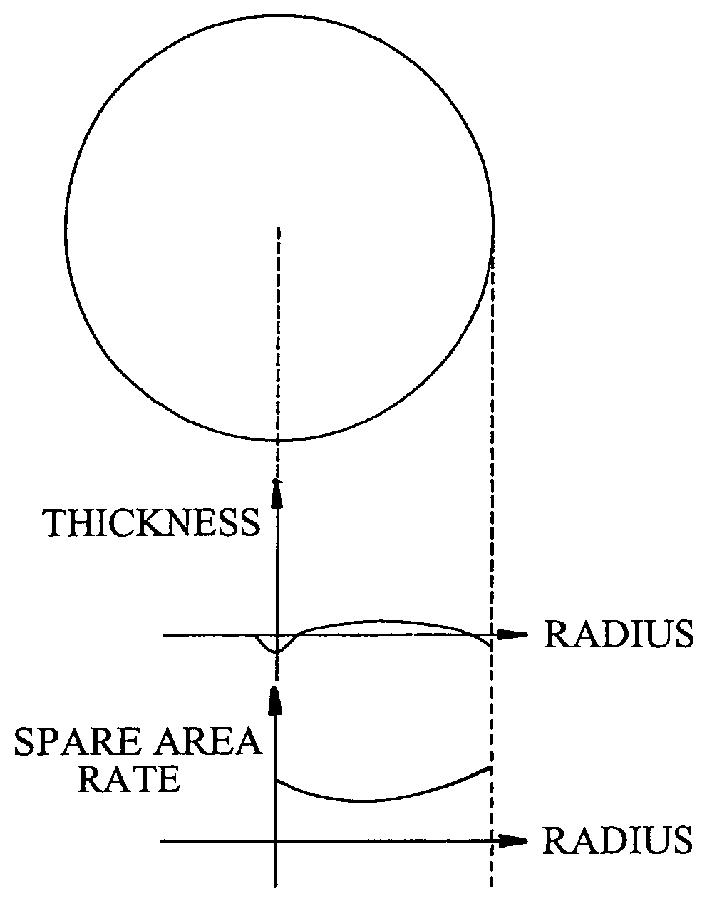
[0023] In the optical disc formed according to an aspect of the present invention in view of the above construction, the spare area rates provided for respective zones are not constantly allotted per zone, but are variably provided per zone to enable to deal with a liably-occurring defect in accordance with the thickness variation of the disc, thereby improving overall reliability of the disc.

Problems solved by technology

However, in employing the optical recording system, reliability of the recording substance of the optical disc, which is the recording medium, is inferior to the reliability of the magnetic disc.
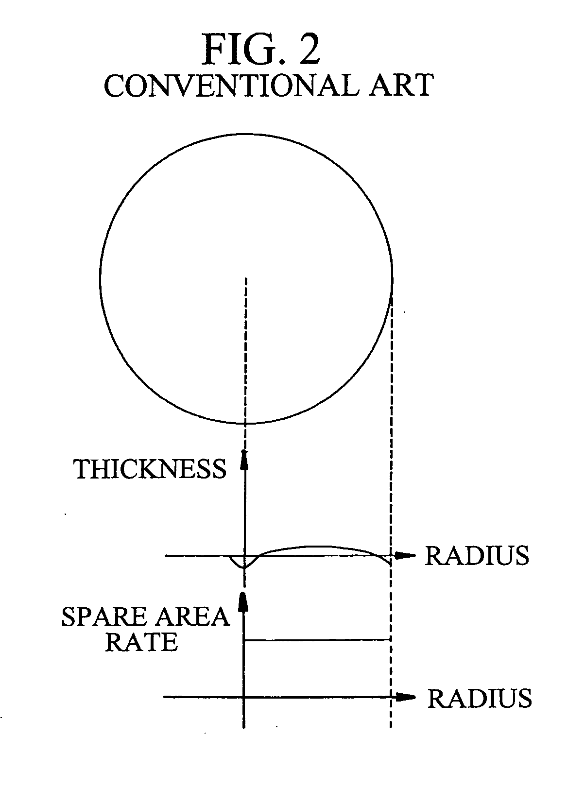
Furthermore during the injection molding for fabricating a substrate of the optical disc, which is formed of a plastic, the inner diameter portion and outer diameter portion of the disc are optically inconsistent due to the differences in resin temperature, cooling time, etc.
Additionally, it is a general point of view that the inconsistency is difficult to be completely eliminated.
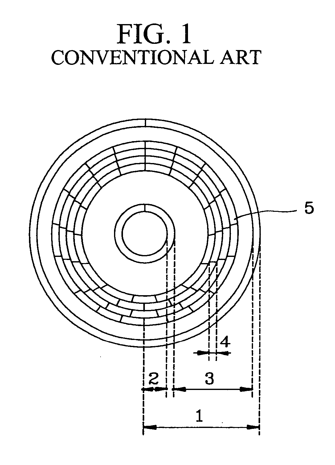
Consequently, since the defect occurring rates at specific points of the optical disc differ from one another, a specific zone cannot be used further if the defect within the corresponding zone is increased to employ all replaceable spare areas.
For this reason, the overall disc may not be used without experiencing reduced reliability due to the increase of the defective portions.

Method used


Image

  • Optical disc having variable spare area rates and method for variably setting the rate of spare areas in the optical disc
  • Optical disc having variable spare area rates and method for variably setting the rate of spare areas in the optical disc
  • Optical disc having variable spare area rates and method for variably setting the rate of spare areas in the optical disc

Examples


Embodiment Construction

[0029] When arranging the rates of spare areas in the present invention, the total quantity of the spare areas during fabrication of an optical disc according to the present invention is set to be identical to that of the optical disc that has the typical spare areas. Also, in arranging the spare areas, it is constructed such that the sizes of the spare areas arranged onto the inner circumferential portion or outer circumferential portion are relatively larger than those of the spare areas arranged onto the center portion by considering the above-mentioned thickness characteristics of the recording layer of the optical disc, as shown in FIG. 3. In the present invention, the term “spare area rate” means the rate of a spare area to a zone area.

[0030] However, the present invention is not limited to the above-described embodiment, but can be applied to the optical disc that does not have the typical spare areas.

[0031] A fabricating method of the optical disc is largely performed by s...


PUM


Abstract

In a method for setting variable areas of an opical disc which variably sets spare area rates of a prescribed quantity provided for preparing a liably-occurring recording error due to a defect of the optical disc having the variable spare areas, the total quantity of the spare areas installed to the optical disc may be the same as the prescribed quantity. Also, the size rates of the spare areas are variably set in the radius direction by centering about a center portion of the optical disc. Particularly, the more spare area rates are given to the inner circumferential portion and outer circumferential portion, and the less spare area rates are given to the center portion which is relatively stable portion, thereby minimizing the defect occurring rate to decrease the number of defective discs.

Description

[0001] This application is a continuation of co-pending application Ser. No. 09 / 055,240, filed on Apr. 6, 1998 (now allowed), and for which priority is claimed under 35 U.S.C. § 120; and this application claims priority of Application No. 19695 / 1997 filed in Republic of Korea on May 21, 1997 under 35 U.S.C. § 119; the entire contents of all are hereby incorporated by reference.BACKGROUND OF THE INVENTION [0002] 1. Field of the Invention [0003] The present invention relates to an optical disc having spare areas and a method therefor, and more particularly to a method for variable setting the rate of spare areas of an optical disc and an optical disc provided with the variable spare area rates. [0004] 2. Description of the Background Art [0005] The recent development of the information industry increases the need for techniques capable of recording information of high density and large quantity. Especially, by entering the multimedia era, a remarkably rapid technical development has b...

Claims


Application Information

Patent Timeline
IPC IPC(8): G11B20/12G11B7/007G11B7/24G11B20/18
CPCG11B7/007G11B2220/20G11B20/1883G11B7/24076
Inventor YEO, WOON-SEONG
Owner LG ELECTRONICS INC
Learn More