
Toner image carrying member and manufacturing method thereof, and electrophotographic apparatus

Active Publication Date: 2005-03-31
CANON KK
View PDF14 Cites 20 Cited by
  • Summary
  • Abstract
  • Description
  • Claims
  • Application Information

AI Technical Summary

Benefits of technology

An object of the present invention is to provide a toner image carrying member which can ensure high cleaning performance and also suppress entanglement of a cleaning blade when used in an electrophotographic apparatus employing a blade cleaning system, a method for manufacturing the toner image carrying member, and an electrophotographic apparatus equipped with the toner image carrying member.

Problems solved by technology

A significant problem arising in connection with electrophotographic apparatuses is how to reliably clean away (remove) toner (hereinafter referred to as “transfer residual toner”) that remains on an outer peripheral surface of a toner image carrying member such as an electrophotographic photosensitive member and an intermediate transfer member without being transferred (including both primary transfer and secondary transfer).
However, when the inventors of the present invention conducted a cleaning performance test by using in combination the blade cleaning method and an intermediate transfer member (an intermediate transfer belt) shaped into an endless belt and whose outermost layer (the layer nearest to the outer peripheral surface) was formed through dip coating and whose outer peripheral surface had a ten-point average roughness of 0.1 μm, the cleaning blade got entangled in the rotating intermediate transfer belt during the test, resulting in damage.
That is, while the cleaning blade can remove transfer residual toner in a favorable manner when a toner image carrying member such as an intermediate transfer member is formed to have an outer peripheral surface that is highly smooth, such an arrangement also involves a problem in that the cleaning blade becomes more liable to be entangled in the toner image carrying member that is rotating.

Method used


Image

  • Toner image carrying member and manufacturing method thereof, and electrophotographic apparatus
  • Toner image carrying member and manufacturing method thereof, and electrophotographic apparatus
  • Toner image carrying member and manufacturing method thereof, and electrophotographic apparatus

Examples


example 1

Manufacture of Endless Belt 1

A sheet of 50 μm in thickness made of polyvinylidene fluoride (available from Kureha Chemical Industry Co., Ltd.) having carbon black dispersed therein was wound by two turns on the outer periphery of an aluminum cylinder, followed by fitting into a SUS cylinder capable of fitting on while leaving a slight gap (100 μm or slightly more). The sheet was then held between the aluminum cylinder on the inner side and the SUS cylinder on the outer side.

Next, with the sheet being held between the aluminum cylinder and the SUS cylinder, the sheet was uniformly heated up to a melting temperature of polyvinylidene fluoride and then cooled, thus obtaining an endless belt base having a thickness of 100 μm. It is to be noted that the inner peripheral surface of the SUS cylinder was machined by cutting into a finished surface having a saw-toothed configuration with a period of 20 μm and an amplitude of 1 μm in the widthwise direction (in the direction parallel to a...

example 2

Manufacture of Endless Belt 5

A sheet of 50 μm in thickness made of polyvinylidene fluoride (available from Kureha Chemical Industry Co., Ltd.) having carbon black dispersed therein was wound by two turns on the outer periphery of an aluminum cylinder, followed by fitting into a SUS cylinder capable of fitting on while leaving a slight gap. The sheet was then held between the aluminum cylinder on the inner side and the SUS cylinder on the outer side.

Next, with the sheet being held between the aluminum cylinder and the SUS cylinder, the sheet was uniformly heated up to a melting temperature of polyvinylidene fluoride and then cooled, thus obtaining an endless belt base having a thickness of 100 μm. It is to be noted that the inner peripheral surface of the SUS cylinder was machined by buffing, forming a smooth, mirror-finished surface in the widthwise direction of the cylinder.

A solution of an acrylic resin (available from JSR Corporation) added with a water-repellent silicone r...

example 3

Manufacture of Endless Belt 6

An endless belt was prepared in the same manner as the endless belt 5 except for changing the mask having the slits to one having a slit pitch of 100 μm (a ratio between the slit width and the width of a portion which is not the slit was 1:1), thus obtaining the endless belt 6.

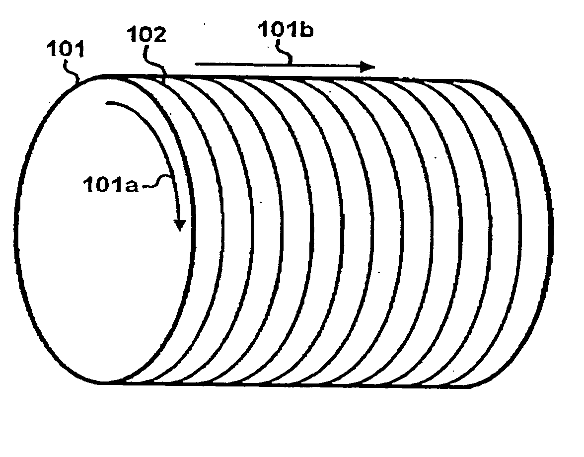
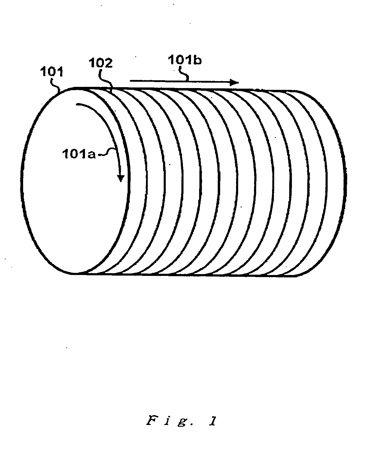
The outer peripheral surface of the endless belt 6 had a configuration substantially like those exemplified in FIGS. 1 and 4.


PUM


Abstract

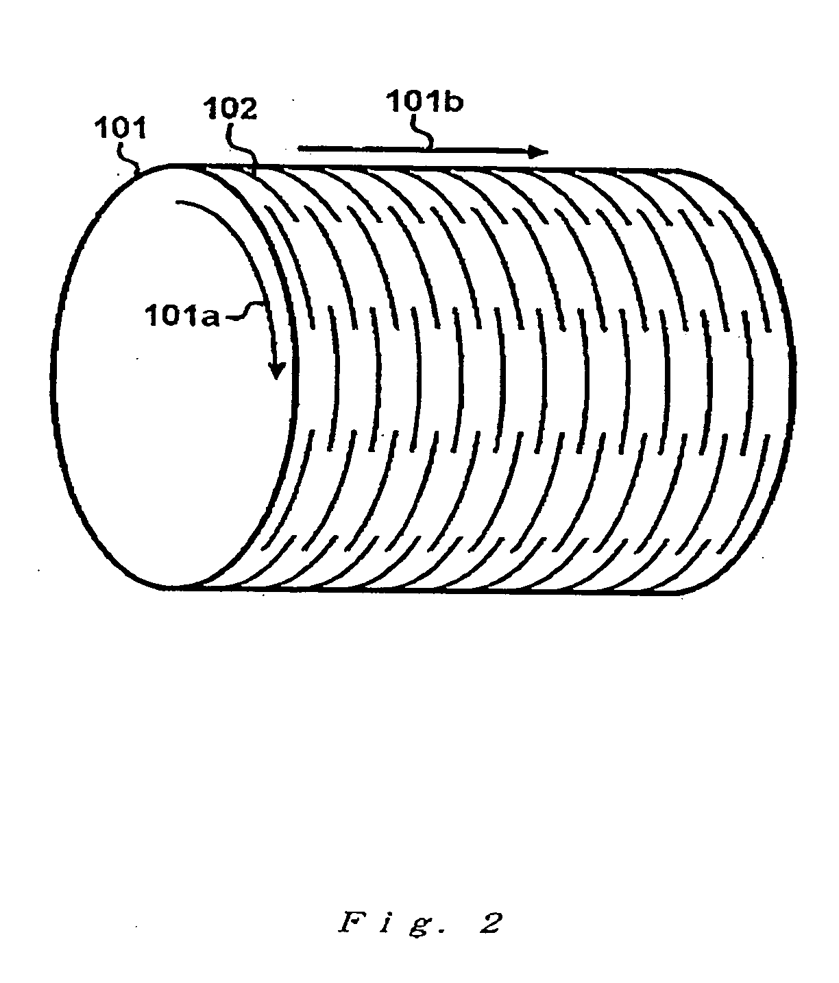
The present invention relates to a toner image carrying member which can be rotationally driven, comprising a plurality of grooves formed on an outer peripheral surface of the toner image carrying member, the plurality of grooves extending along a rotation direction of the toner image carrying member and arranged in an orthogonal direction perpendicular to the rotation direction, and the configuration of the outer peripheral surface of the toner image carrying member in the orthogonal direction is a periodic uneven-configuration; a method for manufacturing the toner image carrying member; and an electrophotographic apparatus having the toner image carrying member.

Description

This application claims priority from Japanese Patent Application No. 2003-337447 filed Sep. 29, 2003, which is hereby incorporated by reference herein. BACKGROUND OF THE INVENTION 1. Field of the Invention The present invention relates to a toner image carrying member, such as an electrophotographic photosensitive member and an intermediate transfer member, and a method for manufacturing the toner image carrying member, and an electrophotographic apparatus having the toner image carrying member. 2. Description of the Related Art There are various types of so-called electrophotographic apparatuses, that is, image forming apparatuses employing an electrophotographic system. Directing attention to the transfer method employed, for example, there are electrophotographic apparatuses employing a method in which a toner image is transferred directly from an electrophotographic photosensitive member to a transfer material (such as paper and OHT) or those employing a method (intermedia...

Claims


Application Information

Patent Timeline
IPC IPC(8): G03G21/00
CPCG03G21/0005G03G2215/00962Y10T428/13G03G2221/1606G03G15/75G03G2221/0026
Inventor MATSUO, YASUHIROKOKUBO, SATOSHI
Owner CANON KK
Learn More