Golfing putter

a technology of golf putter and ball, which is applied in the field of golfing putter, can solve the problems and achieves the effect of reducing the predictability of the direction and distance traveled by the ball

Inactive Publication Date: 2005-03-31
ROBBINS PHILIP CONWAY +2
View PDF15 Cites 7 Cited by
  • Summary
  • Abstract
  • Description
  • Claims
  • Application Information

AI Technical Summary

Benefits of technology

[0023] The golfer may therefore more readily strike a golf ball correctly with said centre of mass above the point of impact with the golf ball.
[0024] The inventor has found that the noise of the strike of the ball against the putting

Problems solved by technology

Although backspin can be beneficial in some circumstances, for most golfers this present difficulties because of the length and speed of the putt being dependant on both the swing of the putter by the golfer and on the potentially variable quality of the pu

Method used


Image

  • Golfing putter
  • Golfing putter
  • Golfing putter

Examples


Embodiment Construction

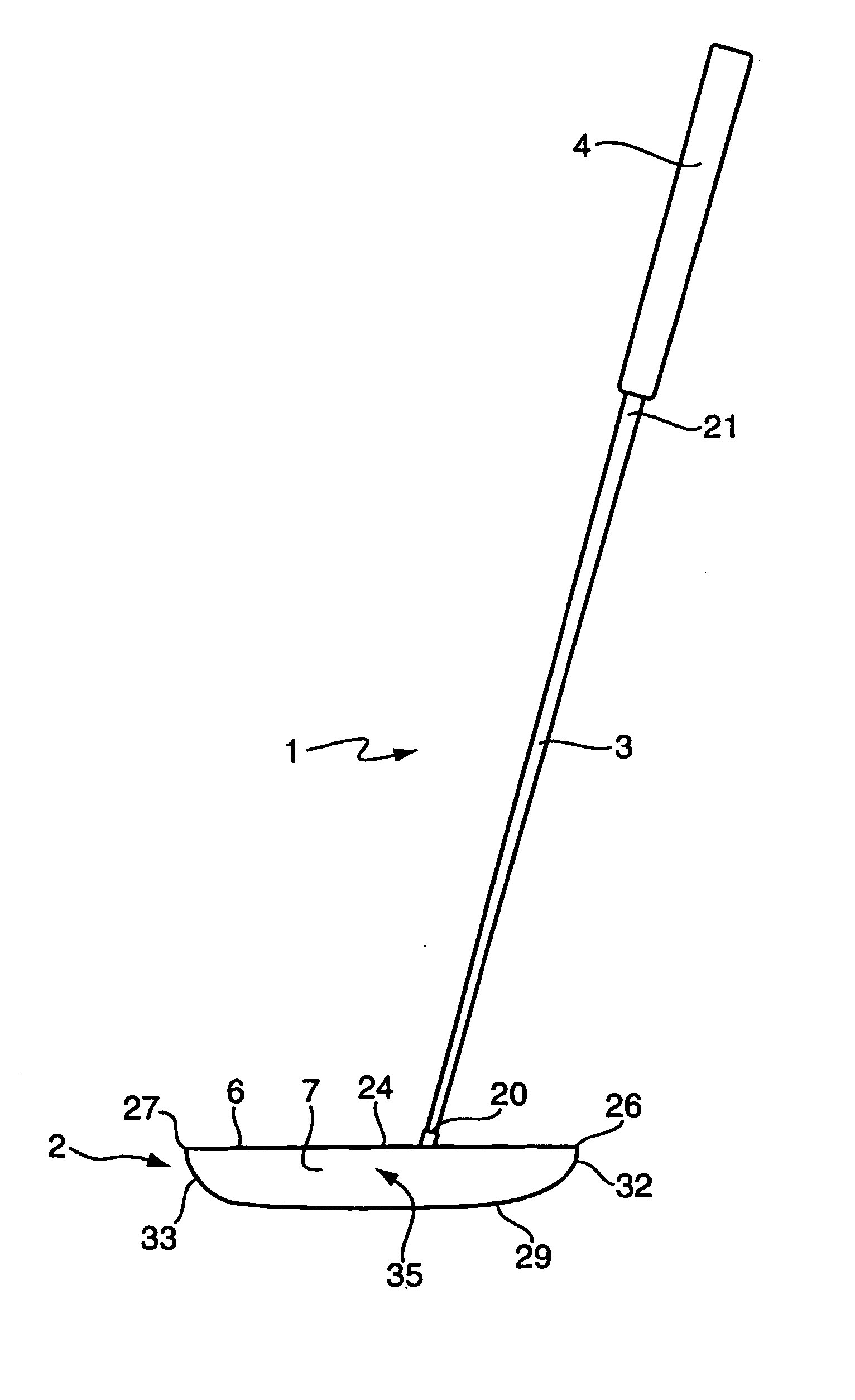
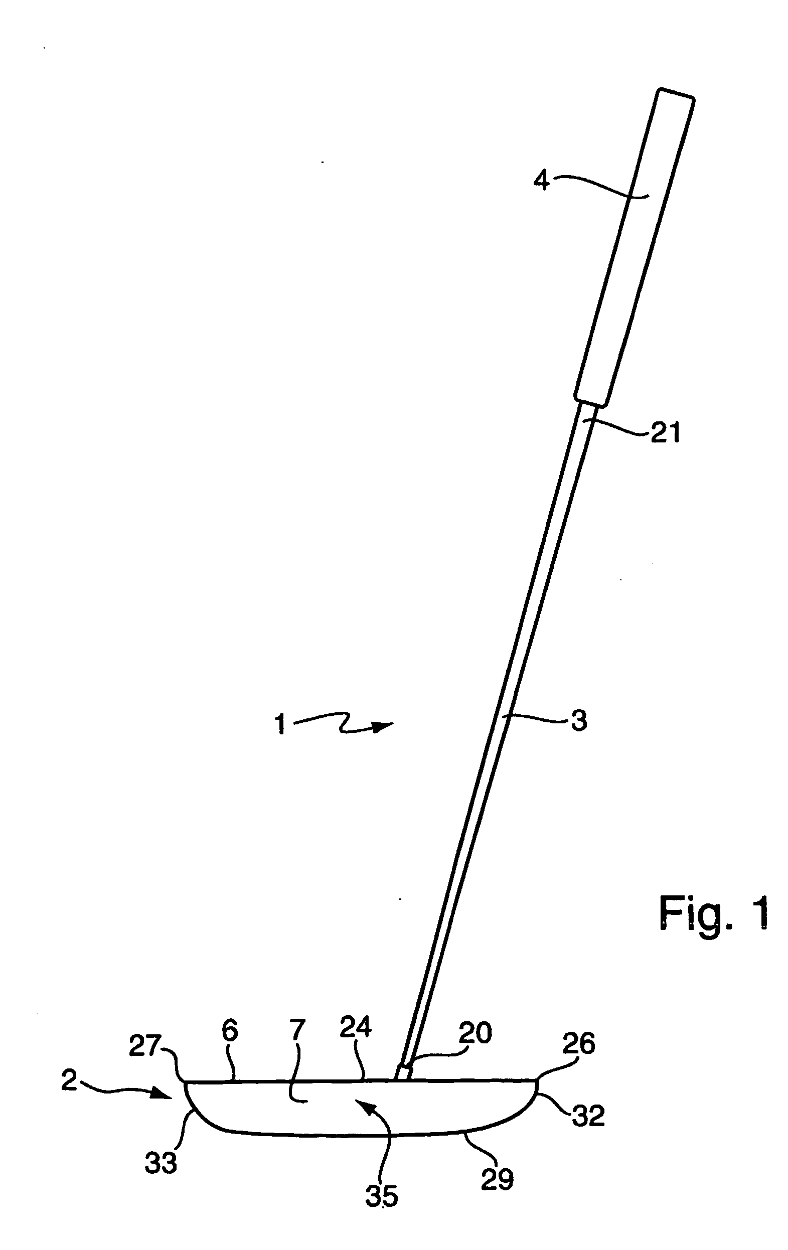
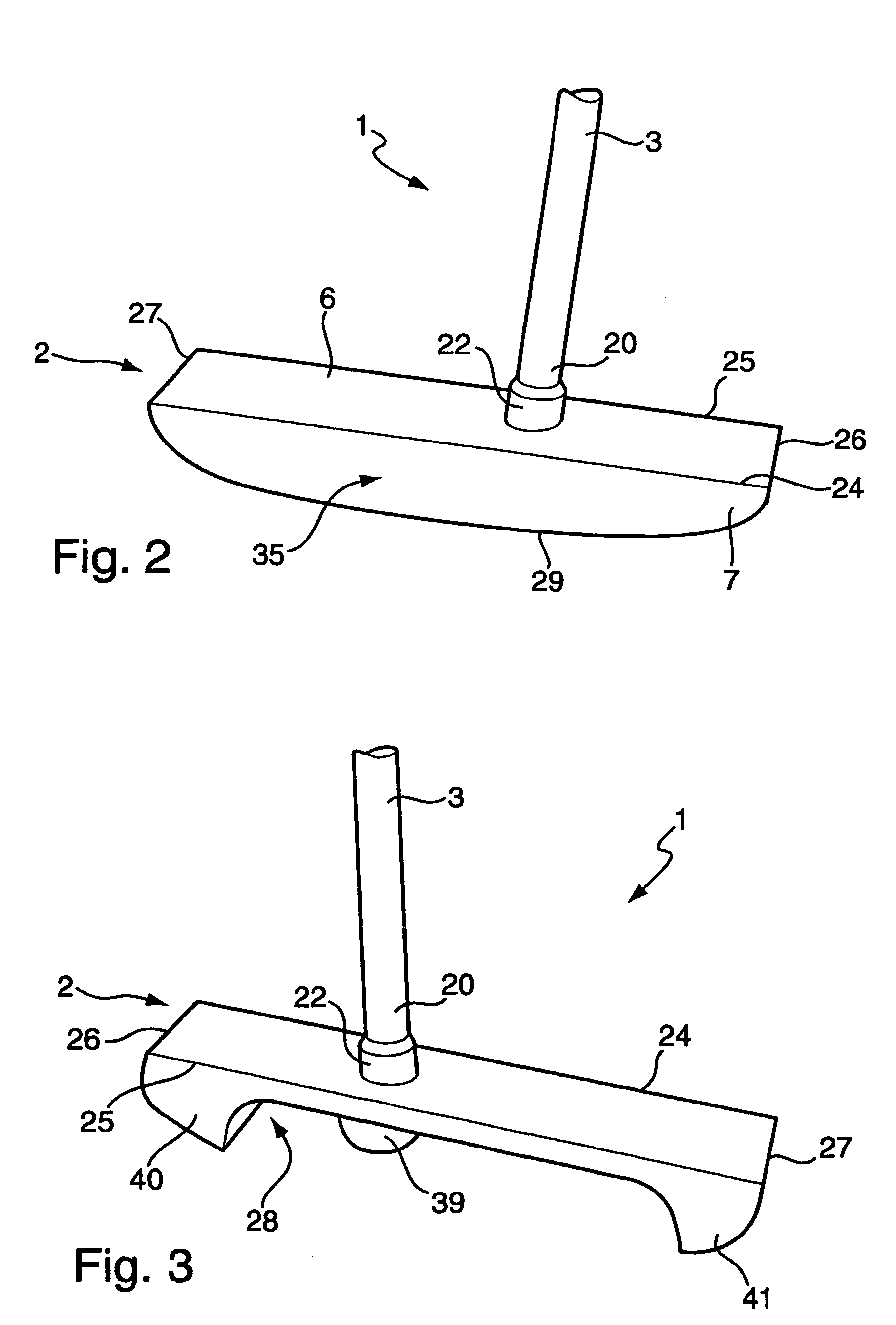
[0037]FIGS. 1, 2 and 3 show a first embodiment of a golfing putter 1. The putter 1 has a tapered chromed steel shaft 3 and a brass putting head 2. A narrow end 20 of the shaft 4 is attached to the brass putting head 2. An opposite wider end 21 of the shaft 3 passes inside a rubber hand grip 4. The shaft 3 and grip 4 are similar to those used for other golfing putters.

[0038] As shown in FIG. 2, the head 2 has a hole 5 into which the narrow end 20 of the shaft 3 is fitted, for example using an interference fit. Optionally, a chromed steel bushing 22 may surround the narrow end 20 of the shaft 3 to make a more secure fit to the hole 5. The shaft 3 may be bonded to the putting head 2 within the hole 5 or bushing 22 by an epoxy resin (not shown).

[0039] The putting head 2 has a rectangular flat top face 6. The shaft 3 is shown at an angle of 15° degrees to a normal of the top face 6 of the putting head 2, but may be between 10° and 45°.

[0040] The top face 6 is bounded by straight paral...


PUM


Abstract

This invention relates to a golfing putter and, more particularly, a golfing putter (1) for helping golfers strike a golf ball (17) consistently without inducing backspin on the ball. The golfing putter (1) comprises a head (2) fixed to a shaft (3). The head (2) has a front face (7) for striking the golf ball (17), and an upper face (6) disposed in use towards the golfer. The vertical centre of mass (8) is behind an upper portion of the front face (7) of the head (2). The head (2) has at least in a central portion (35) of the front face (7) an inverted L-shaped cross-section with the top face (6) forming an upper arm (36) of the L-shape and the front face (7) forming the front arm (37) of the L-shape. The front arm (37) is thinner than the top arm (36). The head therefore has a vertical centre of mass (8) behind an upper third of the front face (7) of the head (2) above the impact point with the golf ball (17).

Description

BACKGROUND [0001] a. Field of the Invention [0002] This invention relates to a golfing putter for striking a golf ball towards a golf hole. [0003] b. Related Art [0004] When playing golf the putter is used to strike a golf ball into the hole from the green or around the green. The golfer addresses the ball with the putter, which is then swung back and forward striking the ball towards the hole on the forward swing. On striking the ball the putter propels the ball towards the hole overcoming the inertia of the stationary ball. [0005] A golfer when preparing to make a putt takes great care in setting up to align the putter and his / her body so as to maximise the effectiveness of the putt. The alignment of the head relative to and eyes along the line of the putt is seen as an important element in this process. [0006] The design of the putting head has a crucial effect on the quality and repeatability of the strike. Modern putters are typically made with some of their mass situated towar...

Claims


Application Information

Patent Timeline
IPC IPC(8): A63B53/04
CPCA63B2053/0408A63B53/0487A63B53/0408
Inventor ROBBINS, PHILIP CONWAYROBBINS, RICHARDGOODA, CHARLES JAMES
Owner ROBBINS PHILIP CONWAY
Why Eureka
Try Eureka