Tongue and groove sheet decking installation kit, including protector block controller shoe and sledgehammer attachment

a technology of protector block controller and installation kit, which is applied in flooring, construction, building construction, etc., can solve the problems achieve the effects of increasing the power of the sledgehammer, facilitating the strike, and enlarge the striking surfa

Inactive Publication Date: 2006-02-02
SOLARI FEDERICK C
View PDF7 Cites 1 Cited by
  • Summary
  • Abstract
  • Description
  • Claims
  • Application Information

AI Technical Summary

Benefits of technology

[0014] The protector block controller shoe is a metal shoe with a handle and a crossbar placed at a comfortable position in front of the operator's foot with the handle above and the crossbar below, so that when the shoe is attached by the crossbar with 1⅝″ decking screws or the like to a 2×4 protector block 36″ to 45″ long, and when the operator's foot is placed in it, it allows the operator to control the protector block from a new, more comfortable and safer position, to slide the protector block back and forth along the edge of the sheet of flooring to be installed, and to pull and hold it tight to the said edge.
[0015] The sledgehammer attachment fits onto a standard 8 lb sledgehammer obtainable at most hardware stores, lumberyards and home centers in North America. The sledgehammer slides into a cup built into the attachment and is held fast by a large u-clamp. The attachment alters one of the striking surfaces of the sledgehammer from parallel to a different angle inward with respect to a line longitudinally through the center of the handle, and enlarges this striking surface. The new angle allows the user to strike the protector block easily and comfortably from the new, more comfortable and safer position. The larger striking surface makes it easier to strike the protector block without missing. And the extra weight of the attachment increases the power of the sledgehammer making it unnecessary to lift it higher than about the waist. Impact is achieved by swinging the hammer with the attachment out beyond the protector block at about waist height and pulling horizontally [as in a tug of war game] as it falls, keeping one's back vertical, and using arm and leg strength mostly. An outrigger arm is attached to the attachment top and extends back to a point on the handle about 6″ from where the handle attaches to the sledgehammer head and is attached with a small clamp that encircles the handle at that point. This is done to spread the increased impact pressure caused by the enlarged striking surface out to a larger section of the handle, much the same way as is done on a standard brush hook(Shelton, Jul. 4, 1882 U.S. Pat. No. 260,423)with a large extended blade.
[0016] This “kit,” as these two combined parts can be called, reduces by a considerable amount the difficulty and danger of this job or process done with the prior method described above and below, almost eliminating the stress created by the prior method on the lower back, and speeding up the process by reducing the number of blows needed, the number of misses that result, the amount of energy needed, and the amount of motion needed, using the prior method. One example is the end joint can now be closed by impacting the open 4′ edge using the exact same tool and exact same motion as joining the 8′ male and female edges. Another example is the whipping action needed to fully utilize the power of the sledgehammer is achieved in a new and easier way as if pulling in a tug of war game from a lower height.

Problems solved by technology

And the extra weight of the attachment increases the power of the sledgehammer making it unnecessary to lift it higher than about the waist.

Method used


Image

  • Tongue and groove sheet decking installation kit, including protector block controller shoe and sledgehammer attachment
  • Tongue and groove sheet decking installation kit, including protector block controller shoe and sledgehammer attachment
  • Tongue and groove sheet decking installation kit, including protector block controller shoe and sledgehammer attachment

Examples


Embodiment Construction

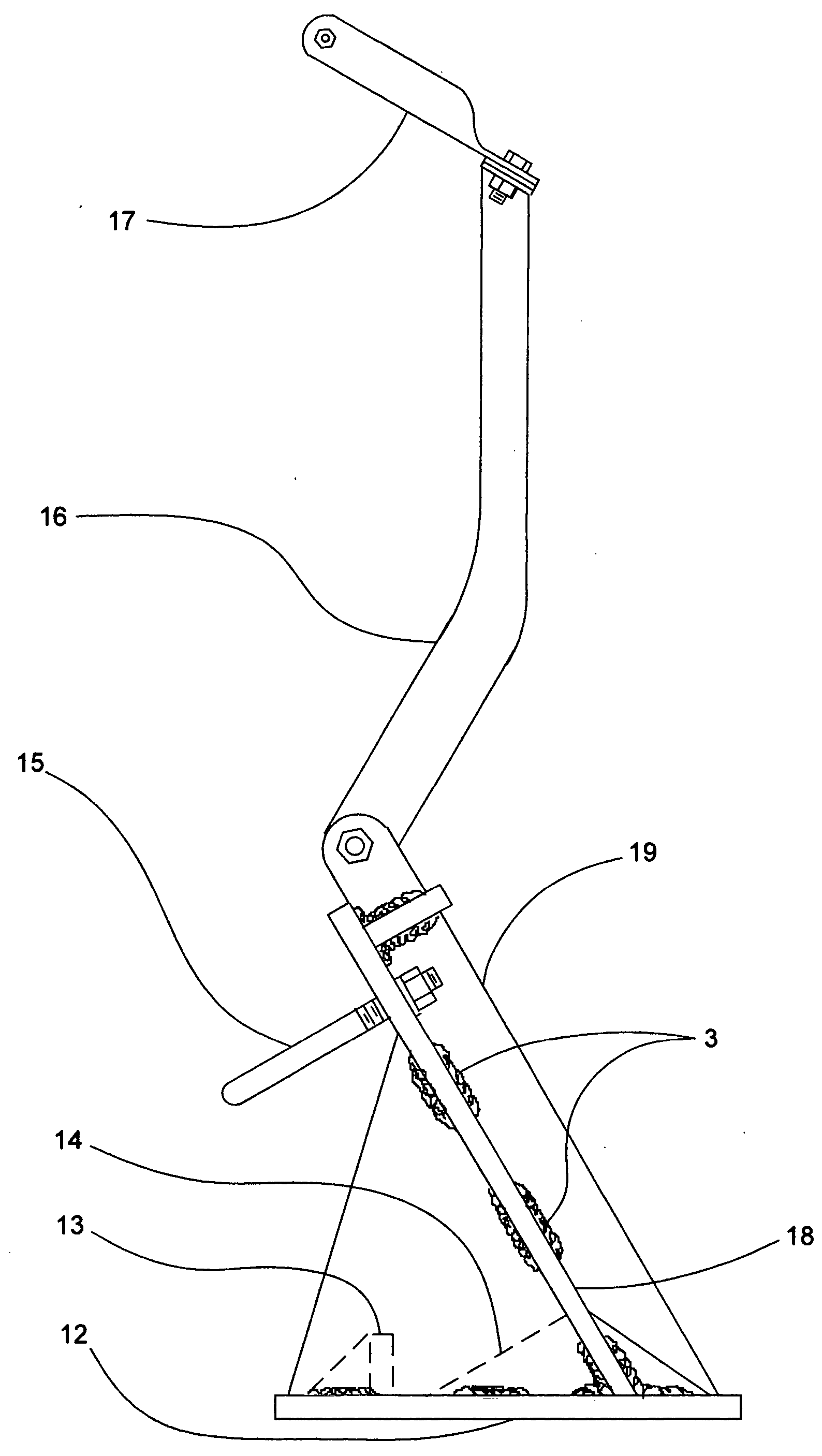
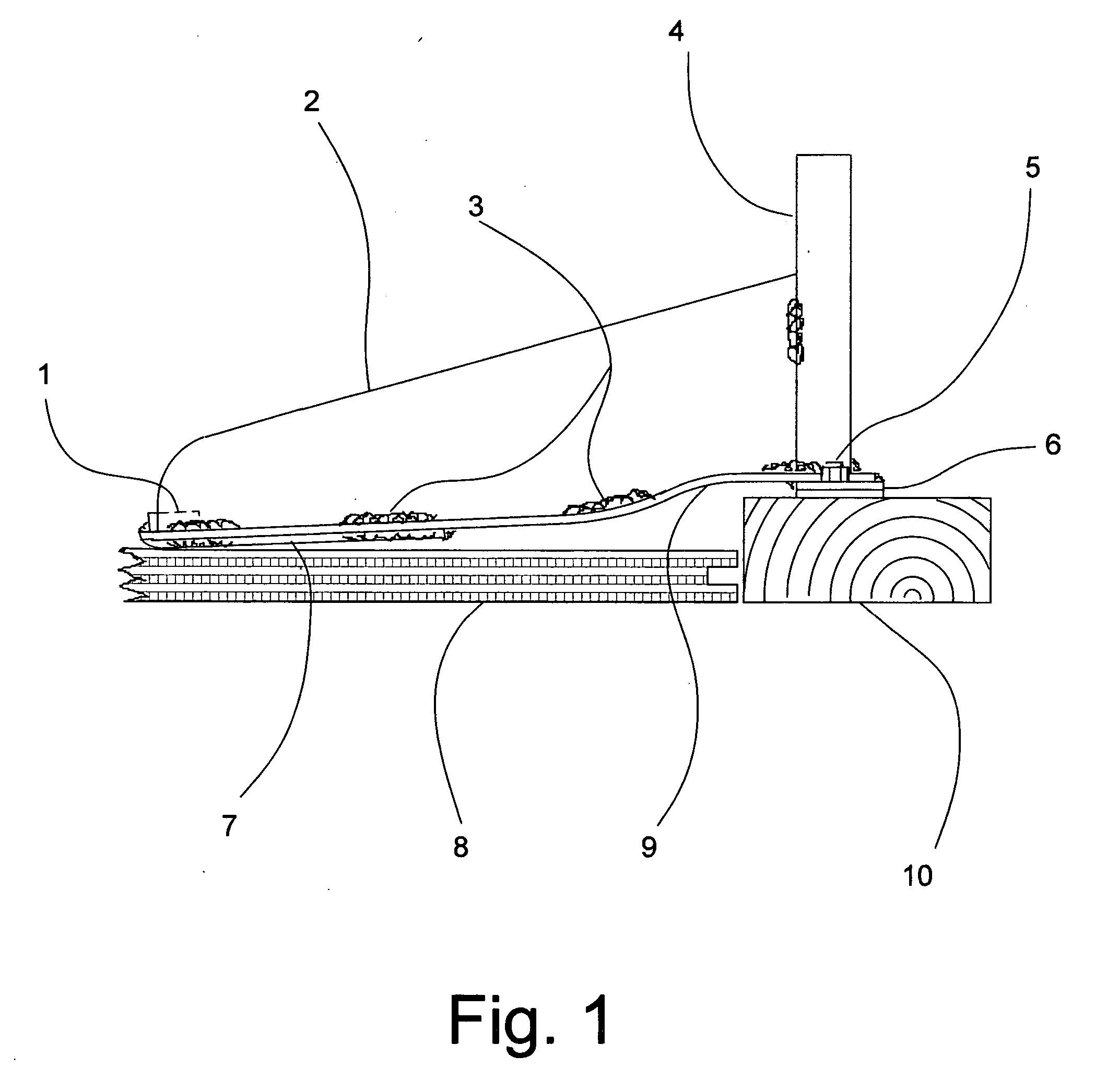
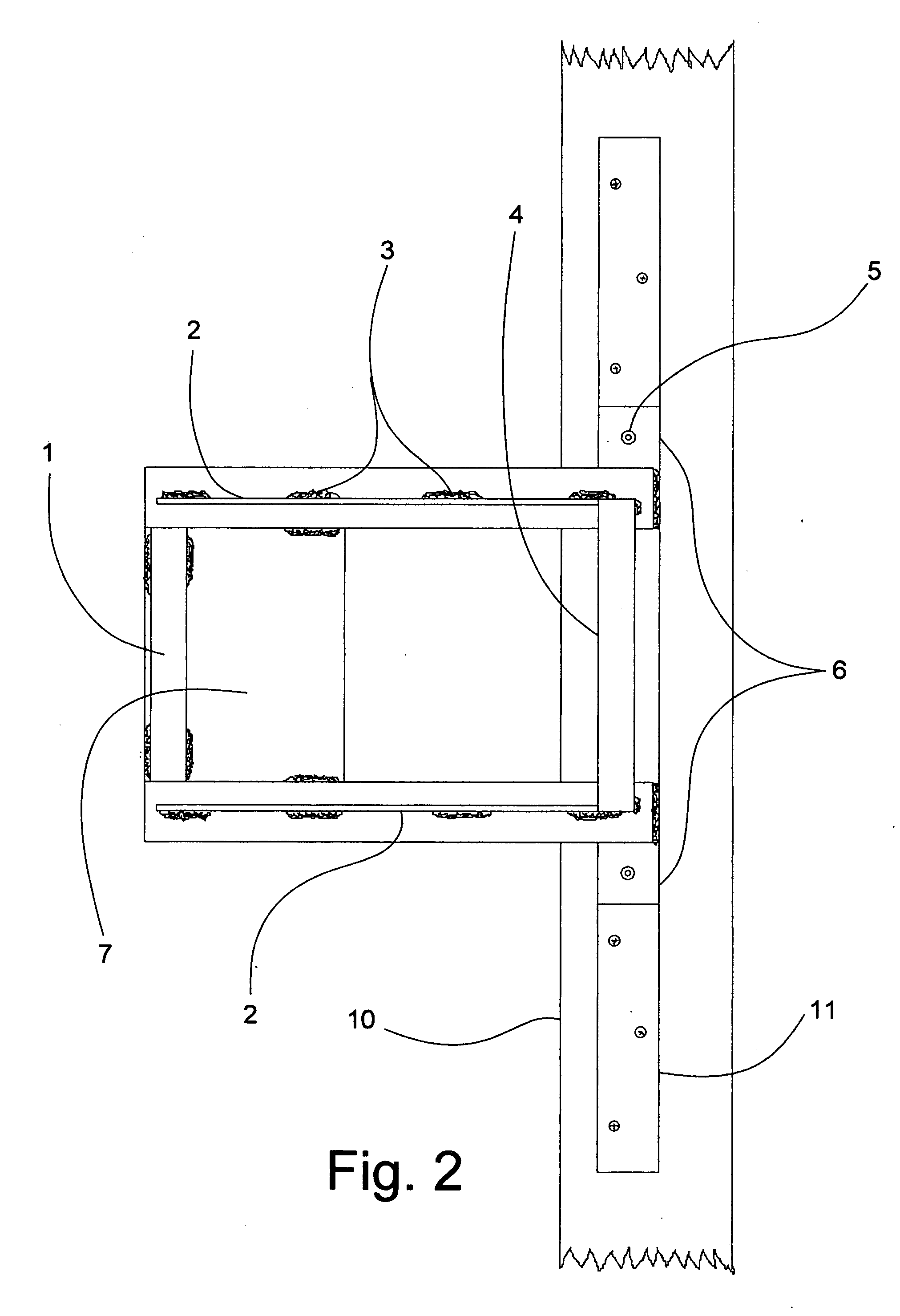
[0047] The invention consists of two parts, the “Protector Block Controller Shoe” and the “Sledgehammer Attachment.”

[0048] The “Protector Block Controller Shoe” (Drawings 1 / 9, 2 / 9, 3 / 9) is basically a treadle body with two sides (2) that extend upwardly from opposite edges of the treadle plate (7) so they are on each side of the ball of the operator's foot when the ball of the foot is placed on the treadle's upper surface. A sturdy handle (4) can be added just beyond and comfortably above the spot where the toes of the operator's foot lie when the operator is using the treadle plate as said. It is recommended that the handle be made out of sturdy enough material, and fastened to the controller shoe body well enough, to withstand errant blows during impacting. A pull bar (1) made of bar stock can be welded or hot riveted close to the back edge of the top surface of the treadle so as to lie under the arch of the foot. The bar stock used should be of sufficient size to enable the opera...


PUM


Abstract

A Kit with a protector block controller shoe being a treadle with two upwardly raised sides, a handle and a crossbar laterally placed before the operator's foot so when the controller shoe is attached by the crossbar to a protector block of standard dimension and material it allows the operator to control the protector block from a new, safer, more comfortable and more advantageous position, and when a sledgehammer attachment has two plates attached width to width at a slightly acute angle with sides to maintain that angle under heavy impact and to provide a pocket for the sledgehammer head to fit into and be held by a clamp and retaining lip in order to change one or more striking surfaces to a new angle inward with respect to a longitudinal line passing through the center of the handle, and to enlarge that surface in order to allow the operator to impact the protector block from the said new, safer, more comfortable and more advantageous position than with any prior art in the same field.

Description

REFERENCES CITED [0001] Dobbertin, Aug. 4, 1987 . . . U.S. Pat. No. 4,683,631 [0002] Roberts, Jul. 25, 1995 . . . U.S. Pat. No. 5,435,610 [0003] Kellenbarger, Sep. 20, 1955 . . . U.S. Pat. No. 2,718,374 [0004] O. A. Johnson, Feb. 12, 1952 . . . U.S. Pat. No. 2,585,013 [0005] Marcon, Jun. 11, 2002 . . . U.S. Pat. No. 6,402,121 [0006] Pasto, Oct. 12, 1999 . . . U.S. Pat. No. 5,964,450 [0007] Lassahn, Aug. 4, 1964 . . . U.S. Pat. No. 3,143,335 [0008] Shelton, Jul. 4, 1882 . . . U.S. Pat. No. 260,423 BACKGROUND OF THE INVENTION [0009] This invention is designed to be used by carpenters and carpenter's helpers in the residential and small commercial building construction trade, specifically in the installation of ¾″ by 4′ by 8′ tongue and groove sub-flooring of various materials, including plywood and pressed, particle board. These sheets or boards are installed with glue and nails on top of joists, frame members or timbers that create the “support” for the floor this sub-flooring become...

Claims


Application Information

Patent Timeline
Patent Type & Authority Applications(United States)
IPC IPC(8): E04F15/00
CPCE04F21/22
Inventor SOLARI, FEDERICK C.
Owner SOLARI FEDERICK C
Why Eureka
Try Eureka