
Tampon applicator

Inactive Publication Date: 2005-03-31
EVEREADY BATTERY CO INC
View PDF63 Cites 30 Cited by
  • Summary
  • Abstract
  • Description
  • Claims
  • Application Information

AI Technical Summary

Benefits of technology

[0012] It is yet another object of the present invention to provide such a tampon applicator barrel in which the substantially flattened fingergrip area results in a finger and a thumb hold that enables the user to overcome the expulsion force exerted on the applicator barrel.
[0015] These and other objects of the present invention will be appreciated from a tampon having an applicator barrel adapted to house a pledget, and especially a radially expanding pledget, and to receive a plunger that is adapted to expel the pledget from the barrel. The applicator barrel has a fingergrip area with at least one set of diametrically opposed, substantially flattened, convex, or concave surfaces. These surfaces have at least one gripping structure to enhance the gripping characteristics of the applicator. The fingergrip area with at least one gripping structure allows the user to hold securely the applicator during insertion and removal, and more importantly, during expulsion of the pledget from the barrel.BRIEF DESCRIPTION OF THE DRAWINGS

Problems solved by technology

Such barrel deformation causes significant friction amongst the pledget, barrel, and plunger, thereby significantly impeding the expulsion of the pledget from the barrel.
However, the gripping structure disclosed is limited to rows of ribs.

Method used


Image

  • Tampon applicator
  • Tampon applicator
  • Tampon applicator

Examples


Embodiment Construction

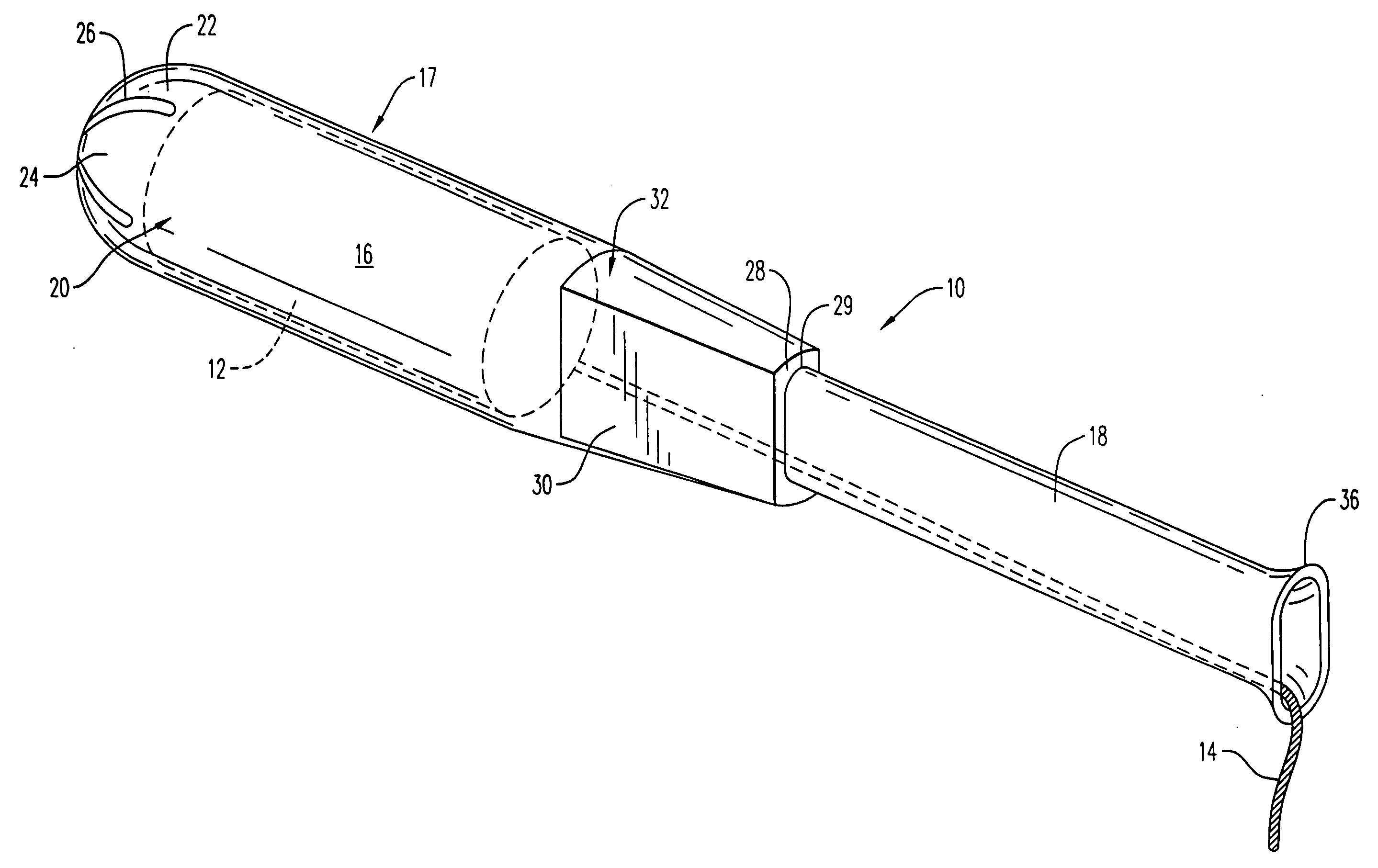
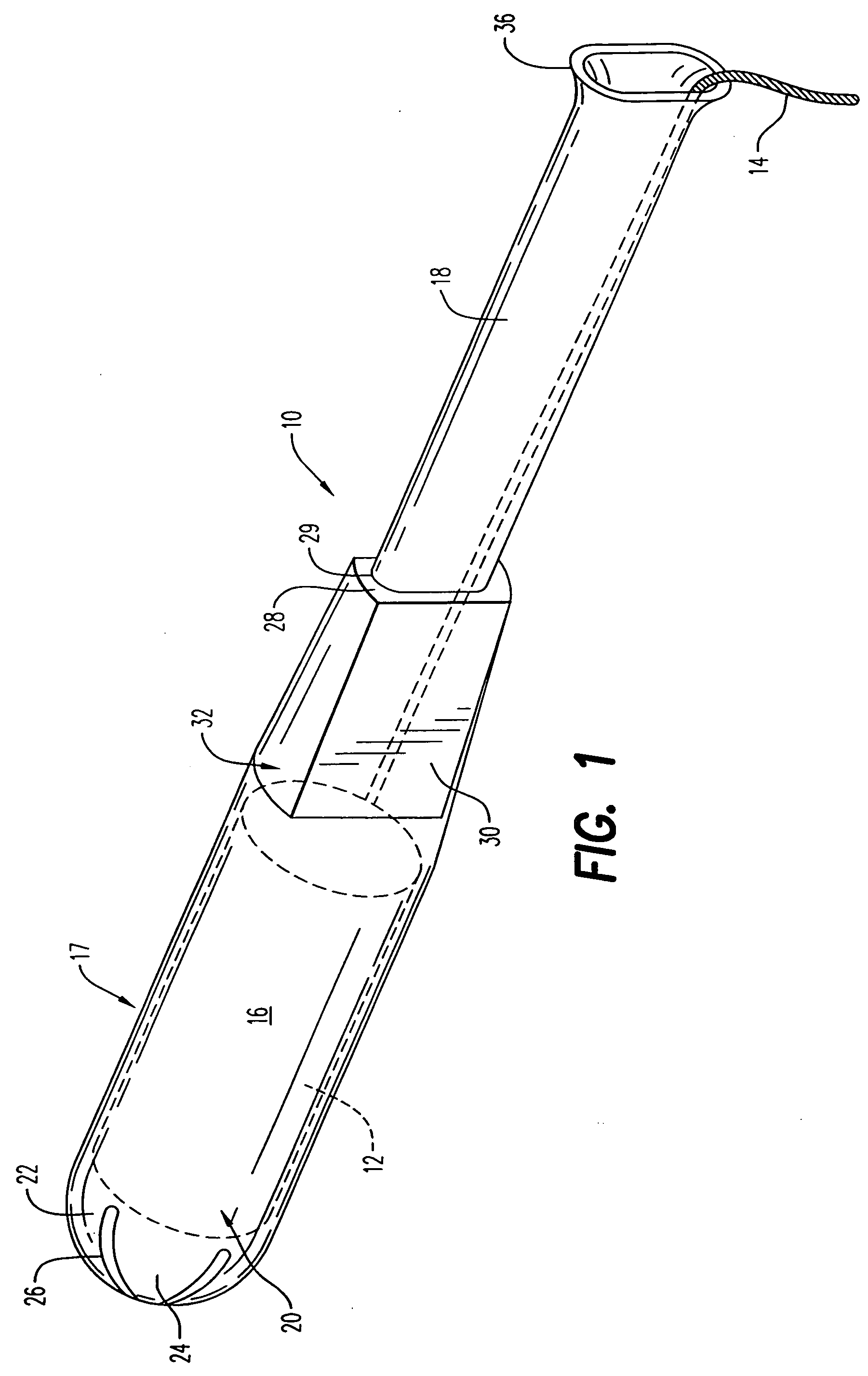
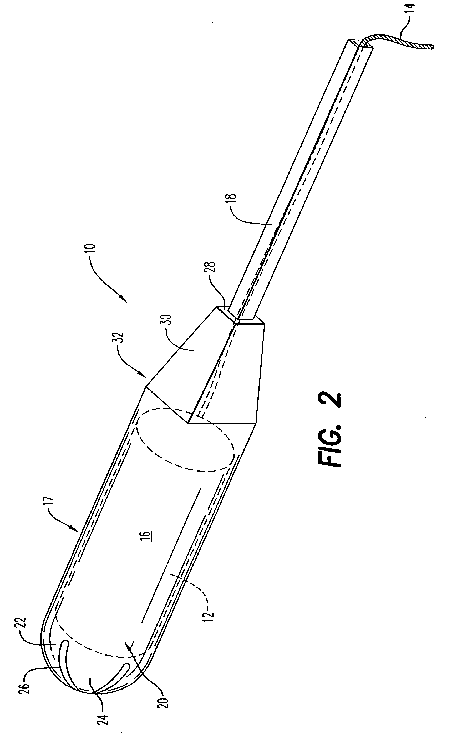
[0025] Referring to the drawings and, in particular, FIG. 1, there is shown a tampon applicator or inserter generally represented by reference-numeral 10. Tampon applicator 10 houses and carries a tampon pledget 12 having a removal string 14. Tampon applicator 10 has a barrel 16 and a plunger 18 telescopically engageable with the barrel.

[0026] The plunger 18 is adapted to eject the pledget 12 from the barrel 16 out of the ejection end 20 of the barrel into the vagina of a user. The barrel 16 has a central body 17 that is preferably tubular and is adapted to house and carry the pledget 12 therein. The barrel 16 has a forward or ejection end 20, and an opposite, rear or plunger-receiving end 32.

[0027] The ejection end 20 of barrel 16 can be open or can have a dome shape. The ejection end 20 preferably has a hemispherical, dome-shaped tip 22. The tip 22 may include a plurality of petals 24, which are preferably formed by a plurality of slits 26. The petals 24 are flexible, enabling t...


PUM


Abstract

A tampon is provided having an applicator barrel adapted to house a pledget, and especially a radially expanding pledget, and receive a telescoping plunger that is adapted to expel the pledget from the barrel. The applicator barrel has a fingergrip area with at least one set of diametrically opposed, substantially flattened surfaces, convex surfaces, concave surfaces, or any combination thereof. These surfaces have at least one gripping structure to enhance the gripping characteristics of the applicator, allowing the user to securely hold the applicator during insertion and removal and during expulsion of the pledget from the barrel.

Description

BACKGROUND OF THE INVENTION [0001] 1. Field of the Invention [0002] The present invention relates to catamenial insertion devices. More particularly, the present invention relates to a catamenial insertion device, such as a tampon applicator, having a fingergrip area with at least one gripping structure. [0003] 2. Description of the Prior Art [0004] A catamenial insertion device or applicator normally has two components, namely a barrel and a plunger that is adapted to telescopically slide in the barrel. The material to be expelled, such as an absorbent pledget, is positioned in the barrel of the applicator. The barrel has a first end for ejection of the pledget, and a second end for receipt of the plunger. To use the tampon applicator, the consumer will position the ejection end appropriately, grasp the barrel, and move or slide the plunger in the barrel towards the ejection end of the barrel to expel the pledget. [0005] Tampon pledgets, and notably radially expanding pledgets, due...

Claims


Application Information

Patent Timeline
IPC IPC(8): A61F13/32A61F13/26
CPCY10S604/904A61F13/26
Inventor JACKSON, DANE R.SIRACUSA, PAUL A.EDGETT, KEITH
Owner EVEREADY BATTERY CO INC
Learn More