Vertebroplasty device having a flexible plunger

a technology of a flexible plunger and a vertebroplasty, which is applied in the field of vertebroplasty, can solve the problems of more force provided by the clinician, and achieve the effect of high torqu

Active Publication Date: 2005-03-31
DEPUY ACROMED INC
View PDF19 Cites 103 Cited by
  • Summary
  • Abstract
  • Description
  • Claims
  • Application Information

AI Technical Summary

Benefits of technology

[0010] The present inventor has noted that the conventional systems having rigid delivery tubes are often limited in tube length because the rigid nature of the delivery tube will tend to produce a high torque upon the inserted cannula when the delivery tube is moved off the axis of the cannula.

Problems solved by technology

However, the pressure drop associated with the length of tube requires that the clinician provide more force to deliver the viscous cement.

Method used


Image

  • Vertebroplasty device having a flexible plunger
  • Vertebroplasty device having a flexible plunger
  • Vertebroplasty device having a flexible plunger

Examples


Embodiment Construction

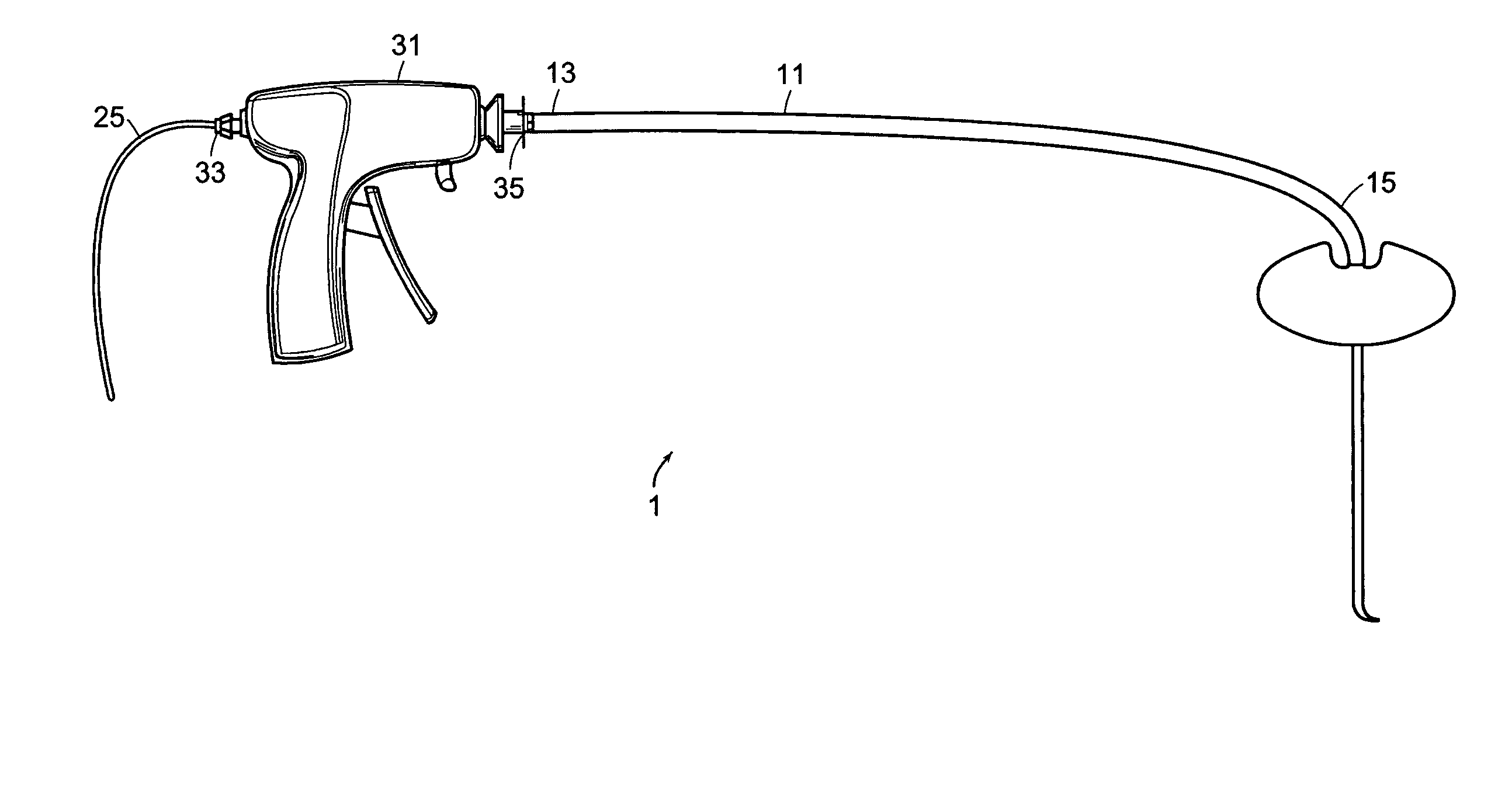
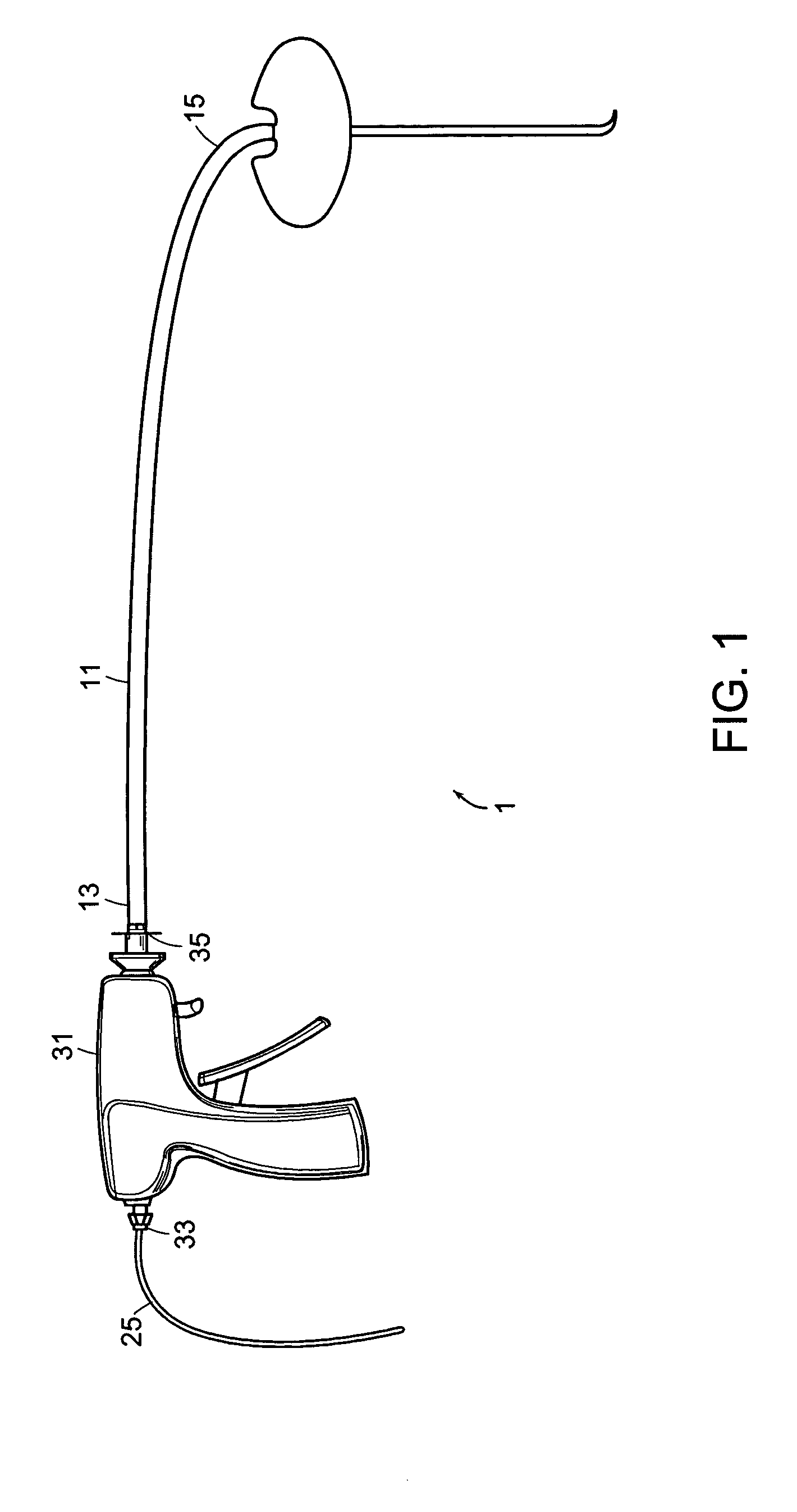
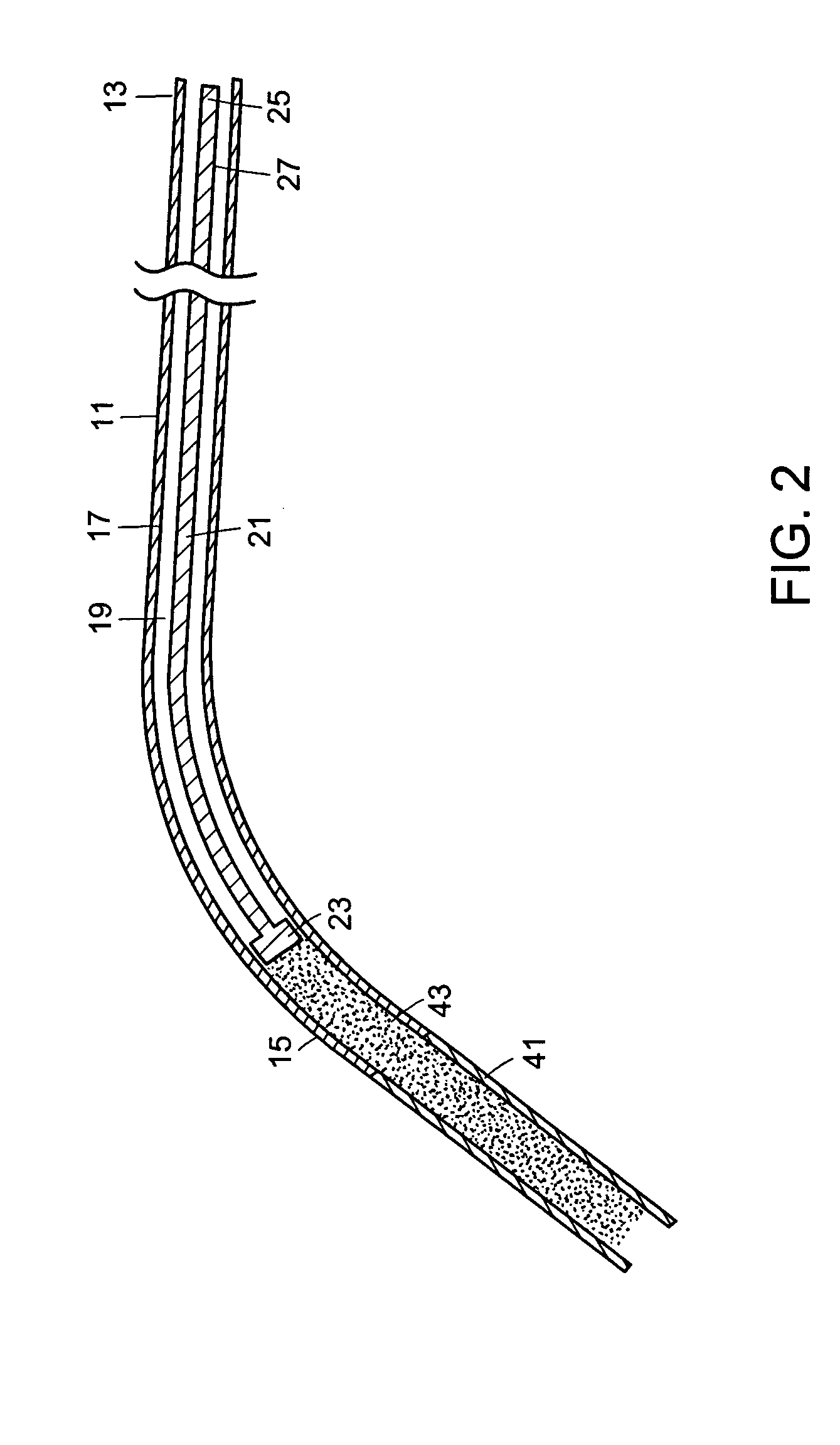
[0025] Now referring to FIGS. 1 and 2, there is provided a device 1 for injecting bone cement, comprising: [0026] a) a flexible delivery tube 11 having a proximal end 13, a distal end 15, and an inner surface 17 defining a bore 19, [0027] b) a flexible plunger 21 having a distal end portion 23 sized for slidable reception in the bore and a proximal end portion 25, [0028] c) an advancing means 31 for distally advancing the plunger, the means located adjacent the proximal end of the flexible delivery tube.

[0029] As noted above, the delivery tube is made to be flexible so as to allow it to be made to a length sufficiently long so as to allow the surgeon to remain outside the fluoroscopy field and to minimize any torque at its distal end produced by off-axis movement relative to the cannula. Preferably, its inner surface is sterile in order to minimize infection.

[0030] Preferably, the tube is made of a non-compliant material that will reduce the amount of cement oozed from the tube in...


PUM


Abstract

A device for injecting bone cement is provided. The device has a flexible delivery tube and a flexible plunger.

Description

BACKGROUND OF THE INVENTION [0001] In vertebroplasty, the surgeon seeks to treat a compression fracture of a vertebral body by injecting bone cement such as PMMA into the fracture site. In one clinical report, Jensen et al., AJNR: 18 Nov. 1997, Jensen describes mixing two PMMA precursor components in a dish to produce a viscous bone cement; filling a 10 ml syringe with this cement, injecting the cement from the larger syringe into a plurality of smaller 1 ml syringes, and finally delivering the viscous cement into a desired area of the vertebral body through needles attached to the smaller syringes. [0002] In order to insure that the injected cement does not travel far from its intended placement location, fluoroscopy is often used by the clinician to monitor the location of the injected cement. However, since delivering the cement by a simple syringe requires placing the clinician's hand in the fluoroscopy field, delivering the cement under direct fluroroscopy would cause the clini...

Claims


Application Information

Patent Timeline
Patent Type & Authority Applications(United States)
IPC IPC(8): A61B17/88
CPCA61B17/8822A61B17/8816A61B17/34A61B17/88
Inventor VOELLMICKE, JOHN
Owner DEPUY ACROMED INC
Why Eureka
Try Eureka