Method and apparatus for providing fixed bandwidth communications over a local area network

a local area network and fixed bandwidth technology, applied in the field of digital networks, can solve the problems of not being able to apply one “plan” or solution to the entire problem, and the complexity of the link construction is too grea

Inactive Publication Date: 2005-03-31
CORPS OF DISCOVERY PATENT HLDG
View PDF79 Cites 137 Cited by
  • Summary
  • Abstract
  • Description
  • Claims
  • Application Information

AI Technical Summary

Benefits of technology

[0007] Generally, the present invention is a method and apparatus for transferring data between a wide area network and a computer system located on an Ethernet type local area network. When characterized as a method, the present invention initially receives data from the wide area network using a digital device that is connected to both the wide area network and the local area network, the data received by the digital device being destined for a computer system attached to the local area network. Next, the digital device receives a signal from systems in the wide area network indicating that the data is to be transferred to and from the computer system at a predetermined guaranteed quality of service (QoS) and bandwidth. Packets that contain the data are then formatted to indicate that the data is to be transmitted at a “guaranteed” rate of throughput higher than the minimum rate. Finally, the packets that contain the data are sent to the computer system, thereby establishing a communication link

Problems solved by technology

Developing equipment and methods for dynamically establishing communication links that have a guaranteed amount of bandwidth on a wide area network (such as the Internet) is an ongoing problem for the communic

Method used


Image

  • Method and apparatus for providing fixed bandwidth communications over a local area network
  • Method and apparatus for providing fixed bandwidth communications over a local area network
  • Method and apparatus for providing fixed bandwidth communications over a local area network

Examples


Embodiment Construction

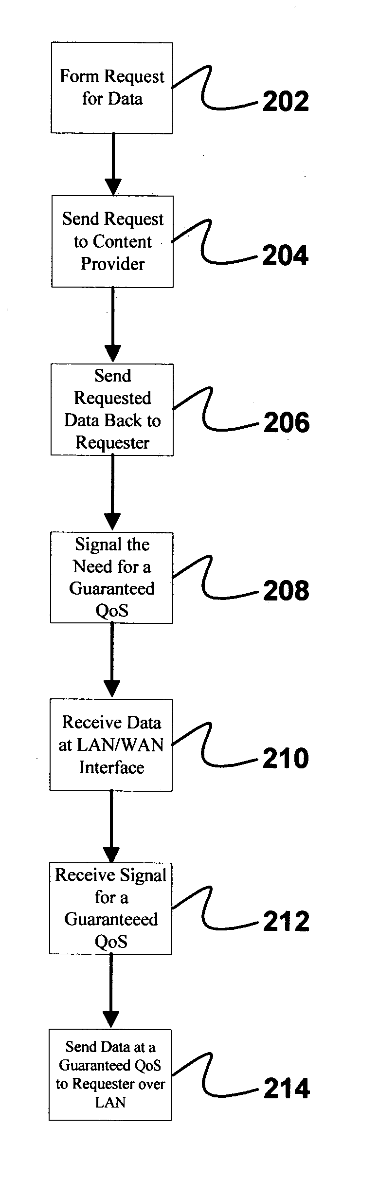
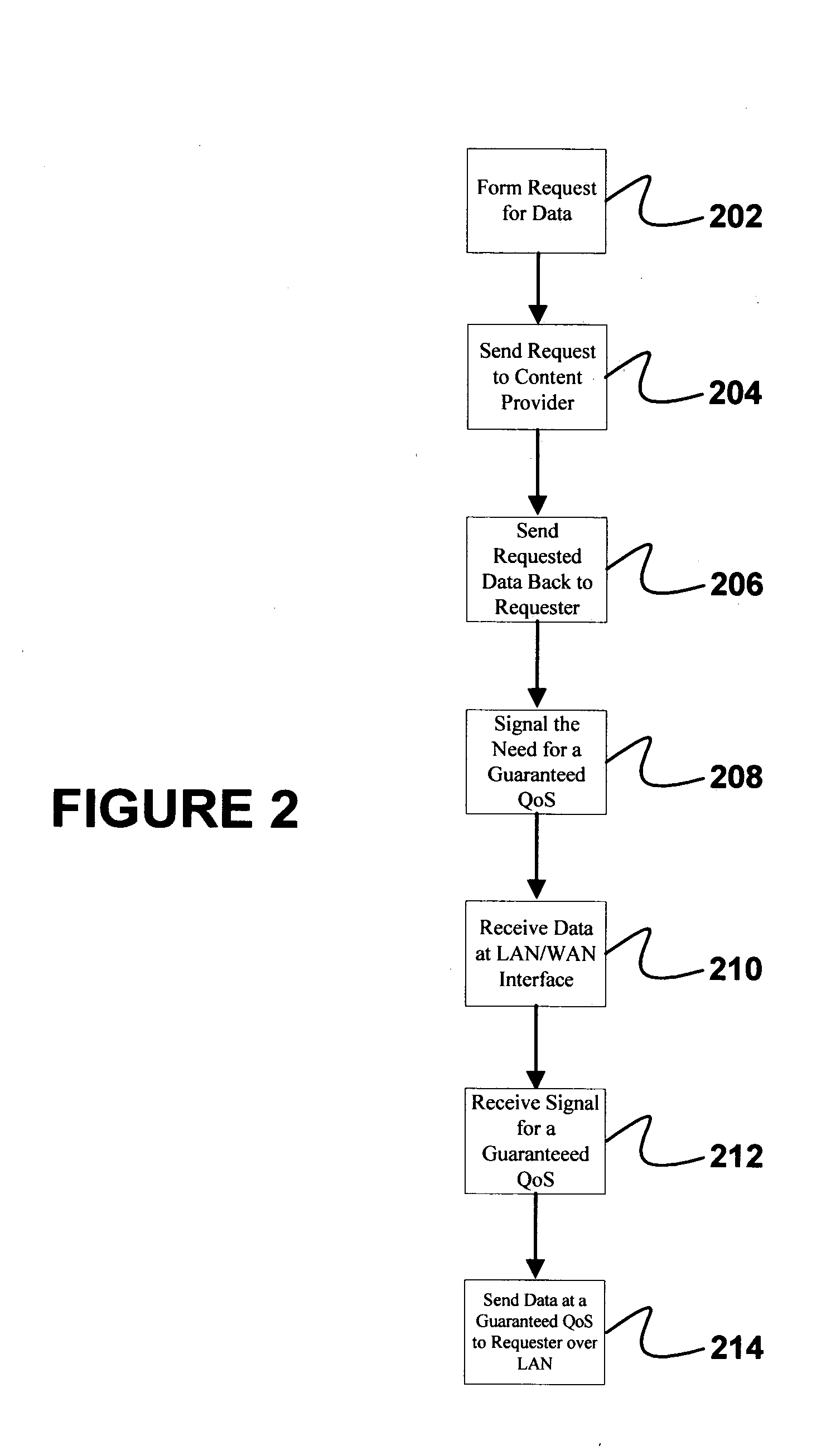
[0012] Generally, the present invention is a method by which a network communication device at the edge of a wide area network (WAN) establishes a communication link, having a guaranteed minimum amount of bandwidth, with computer systems located on an Ethernet network. Initially, the network communication device, which is typically a router, receives a stream of data being sent to a computer systems attached to an Ethernet network. In response to a signal, the router will establish a communication link with the computer system according to the Ethernet provisions that allow for communications to occur at a relatively fixed data rate. Then, the data destined for the computer system is delivered over this link at a relatively fixed rate, thereby allowing for a high QoS (quality of service) level to be maintained.

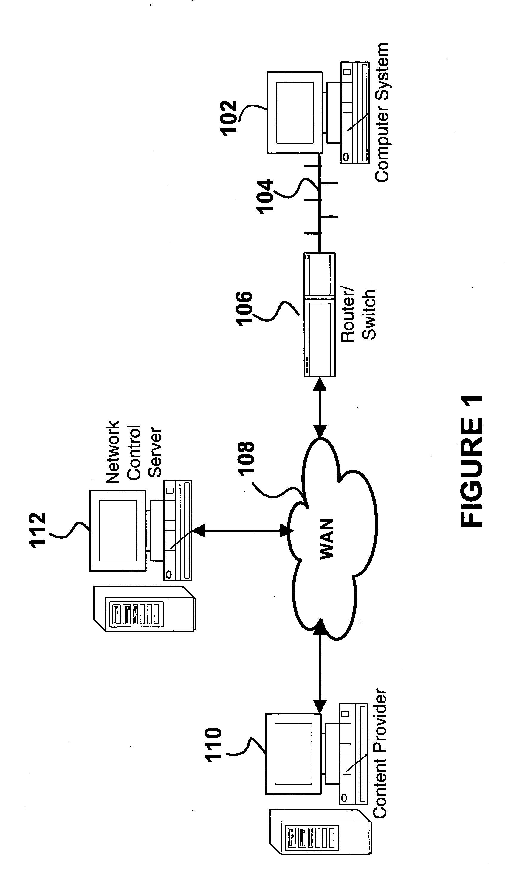
[0013]FIG. 1 shows a computer network upon which the present invention can be implemented. Computer system 102 is attached to a local are network (LAN) 104. LAN 104 is an Eth...


PUM


Abstract

The present invention is a method and apparatus for transferring data between a wide area network and a computer system located on an Ethernet type local area network. When characterized as a method, the present invention initially receives data from the wide area network using a digital device that is connected to both the wide area network and the local area network, the data received by the digital device being destined for a computer system attached to the local area network. Next, the digital device receives a signal from systems in the wide area network indicating that the data is to be transferred to and from the computer system at a predetermined guaranteed quality of service (QoS) and bandwidth. Packets that contain the data are then formatted to indicate that the data is to be transmitted at a “guaranteed” rate of throughput higher than the minimum rate. Finally, the packets that contain the data are sent to the computer system, thereby establishing a communication link for the packet stream between the wide area network and the local area network that transmits data at the guaranteed QoS.

Description

BACKGROUND OF THE INVENTION [0001] The present invention relates generally to a digital network that can dynamically establish communication links between digital devices with a guaranteed quality of service (QoS). More specifically, the present invention enables a digital device located at the edge of a wide area network to establish a communication link that can transmit data at a guaranteed bandwidth to computer systems located on an Ethernet network. [0002] Developing equipment and methods for dynamically establishing communication links that have a guaranteed amount of bandwidth on a wide area network (such as the Internet) is an ongoing problem for the communications industry. As many have come to realize, reliably constructing such links is sufficiently complex and involves so many different systems that no one “plan” or solution can be applied to the entire problem. Instead, solutions are gradually being developed within the framework of the equipment and standards which exi...

Claims


Application Information

Patent Timeline
IPC IPC(8): G06F15/16G06F15/173H04L12/56
CPCH04L47/10H04L47/13H04L49/90H04L47/245H04L47/2408
Inventor RUNDQUIST, WILLIAM A.GOLDEN, MICHAEL E.
Owner CORPS OF DISCOVERY PATENT HLDG
Why Eureka
Try Eureka