Wheel sensor assembly for rail base mounting

a technology for sensors and rail bases, applied in vehicle wheel testing, transportation and packaging, instruments, etc., can solve the problems of insufficient stoutness of mounting brackets to withstand freight traffic conditions, rails experience a depression, and almost a shock, and achieve the effect of reducing price, easy installation, and accurate installation

Inactive Publication Date: 2005-04-07
TRANERGY CORP
View PDF3 Cites 29 Cited by
  • Summary
  • Abstract
  • Description
  • Claims
  • Application Information

AI Technical Summary

Benefits of technology

[0010] In view of the desired goals of the invention claimed herein, a rugged rail-mounted wheel-sensing system is described comprising a steel rail clamp having two blocks mounted on the base of the rail and connected by a pair of bolts. The standard blocks are designed for heavy haul rail (132 RE and above). For use on lighter rail such as 115 RE or 119 RE, an adapter plate is added for accurate installation. The rail-mounted wheel-sensing system further includes a vertically adjustable mounting bracket for mounting sensors or other devices. The bracket is adjustably fixed to one of the clamp blocks. The system is constructed so that only the distance of the sensor below the rail head (approximatel

Problems solved by technology

Rails experience a depression, and almost a shock, when a wheel travels on them.
Presently available wheel sensors are designed for high speed rail travel over 200 miles per hour; however, their mounting brackets are not stout enough to withstand freight traffic conditions.
Currently available sensors require both

Method used


Image

  • Wheel sensor assembly for rail base mounting
  • Wheel sensor assembly for rail base mounting
  • Wheel sensor assembly for rail base mounting

Examples


Embodiment Construction

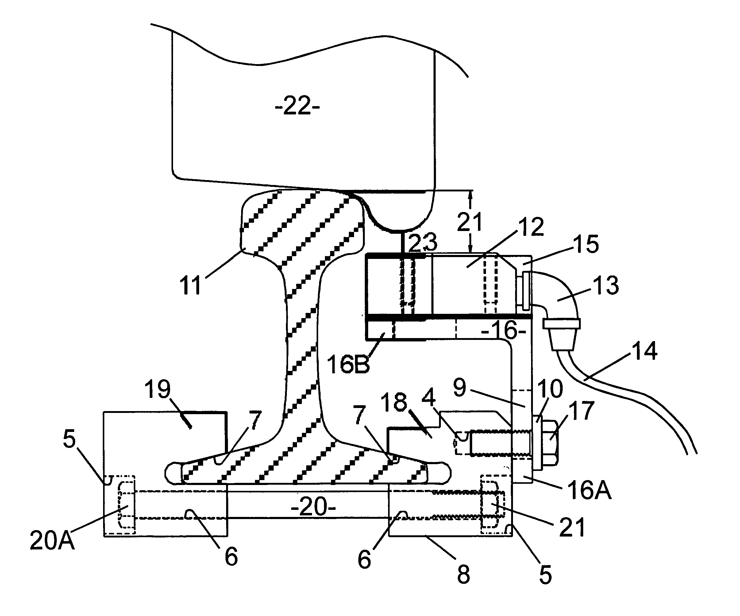
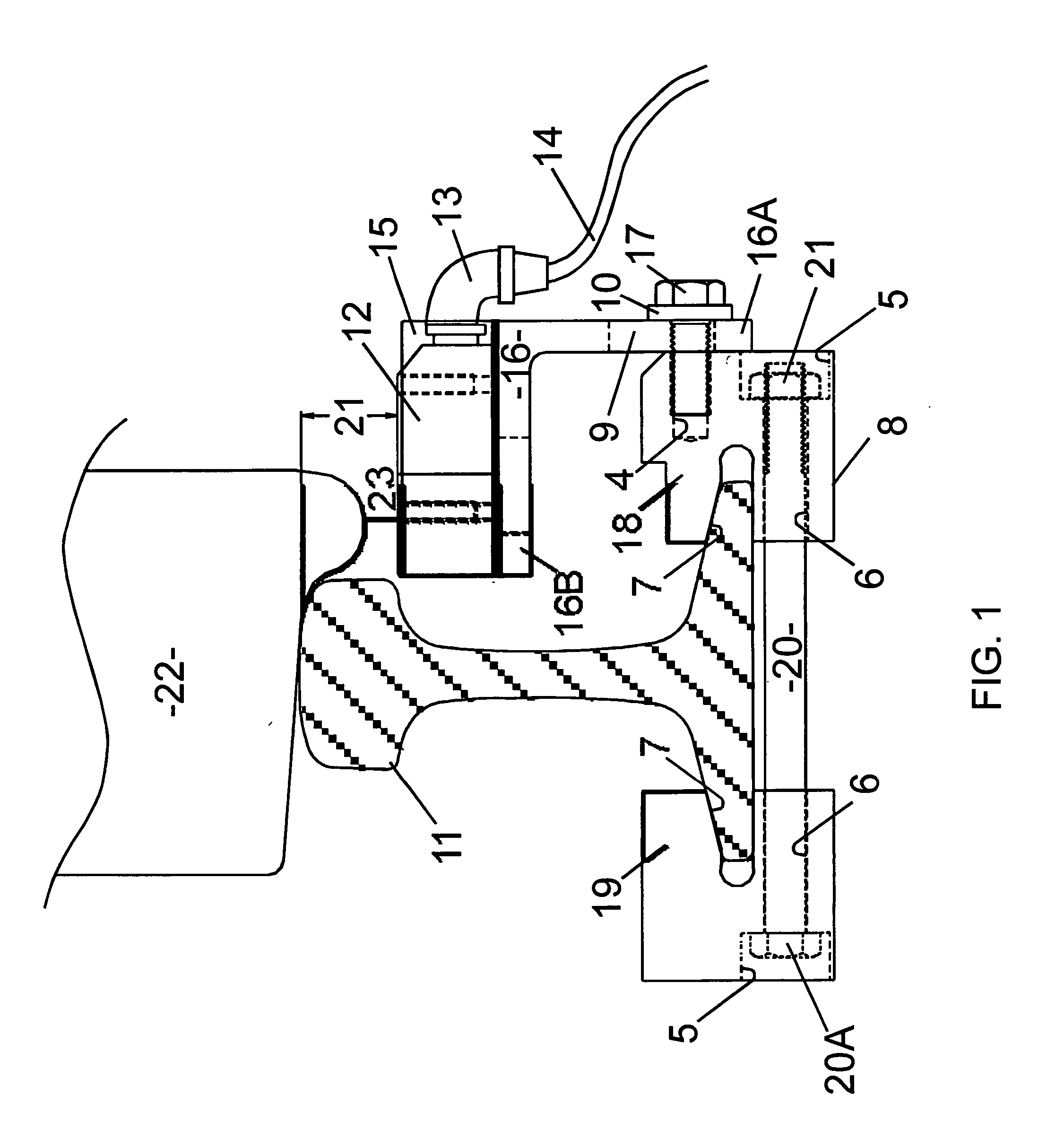
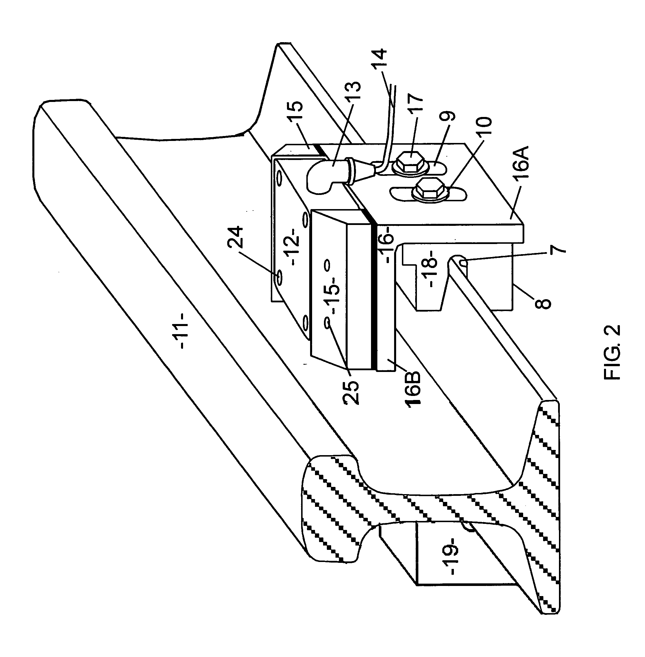
[0017] The present invention is designed to provide a railroad car wheel sensor assembly which is mounted on a rail. It includes a wheel sensor on a mounting bracket attached to a rail clamp. The bracket is vertically adjustable on the clamp. Shields on the bracket provide protection from impacts with articles hanging from passing rail cars. In a preferred embodiment, it is desirable to optimize the specifications of the wheel-sensing system in order to comply with and be best suited for North American rail freight applications. More specifically, the North American rail freight applications require the following:

[0018] Mounting a sensor bracket on the rail web requires drilling holes in the web which can lead to fractured rails. Mounting a bracket on the base of the rail is therefore less damaging and quicker.

[0019] A sensing system should have an extremely rugged sensor mounting clamp and bracket. North American heavy haul traffic has an extreme impact vibration load on rail, pa...


PUM


Abstract

A rail-mounted, wheel-sensing system is shown having a wheel sensor and a rail mounting platform. The system includes a rugged steel rail clamp including two blocks mounted on the base of the rail by a pair of bolt extending under the rail. One block is connected to a vertically adjustable mounting bracket for carrying a sensor or other device. The mounting bracket includes a platform for the sensor. Two shields on the platform protecting a sensor mounted between them. An adapter plate may be added between the mounting bracket and the clamp for installation on lighter or heavier rails.

Description

BACKGROUND OF THE INVENTION [0001] The present invention relates generally to a railroad car wheel sensor assembly, and more particularly, to a rail-mounted, wheel-sensing system having a wheel sensor and a mounting bracket therefor. [0002] Today's railroads need to detect the presence of wheels at certain locations on the track. Electrically inductive sensors are often used for this purpose. These sensors, along with their mounting systems, need to be treated as an integrated, matched system this is optimized for freight rail in North America. This means accounting for the effects of heavy haul loads on Class II, III or IV tracks at moderate speeds (10 to 70 miles per hour) and achieving a product cost point which is lower than that of conventional systems. [0003] Rails experience a depression, and almost a shock, when a wheel travels on them. It is therefore necessary that any rail-mounted system for wheel sensors be very rugged and not subject to loosening with vibration over tim...

Claims


Application Information

Patent Timeline
IPC IPC(8): B61L1/02
CPCB61L1/02
Inventor KUMAR, SUDHIRDYAVANAPALLI, VENKAT
Owner TRANERGY CORP
Why Eureka
Try Eureka