Pet food feeder

Inactive Publication Date: 2005-04-07
HAMMER MARKUS
View PDF5 Cites 19 Cited by
  • Summary
  • Abstract
  • Description
  • Claims
  • Application Information

AI Technical Summary

Benefits of technology

[0007] The primary objective of the present invention is to provide a pet food feeder, comprising a connecting member coupled to a support rod, a first connecting surface vertically disposed on the connecting member, a second connecting surface vertically disposed on a containing member of a food bin, a pivotal axis and an axial hole respectively disposed on the first and second connecting surfaces respectively, such that the entire pet food feeder passing through the pivotal ax

Problems solved by technology

Therefore, the pet can only use its mouth or noise to push food to the edge of the bin to centralize the food before eating.
Such arrangemen

Method used


Image

  • Pet food feeder
  • Pet food feeder
  • Pet food feeder

Examples


Embodiment Construction

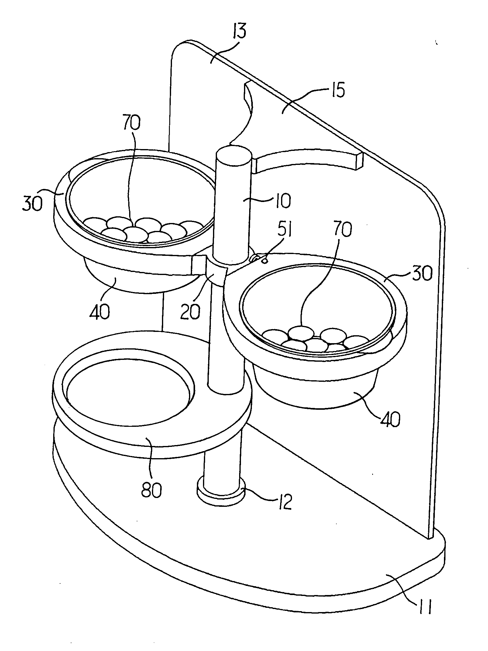
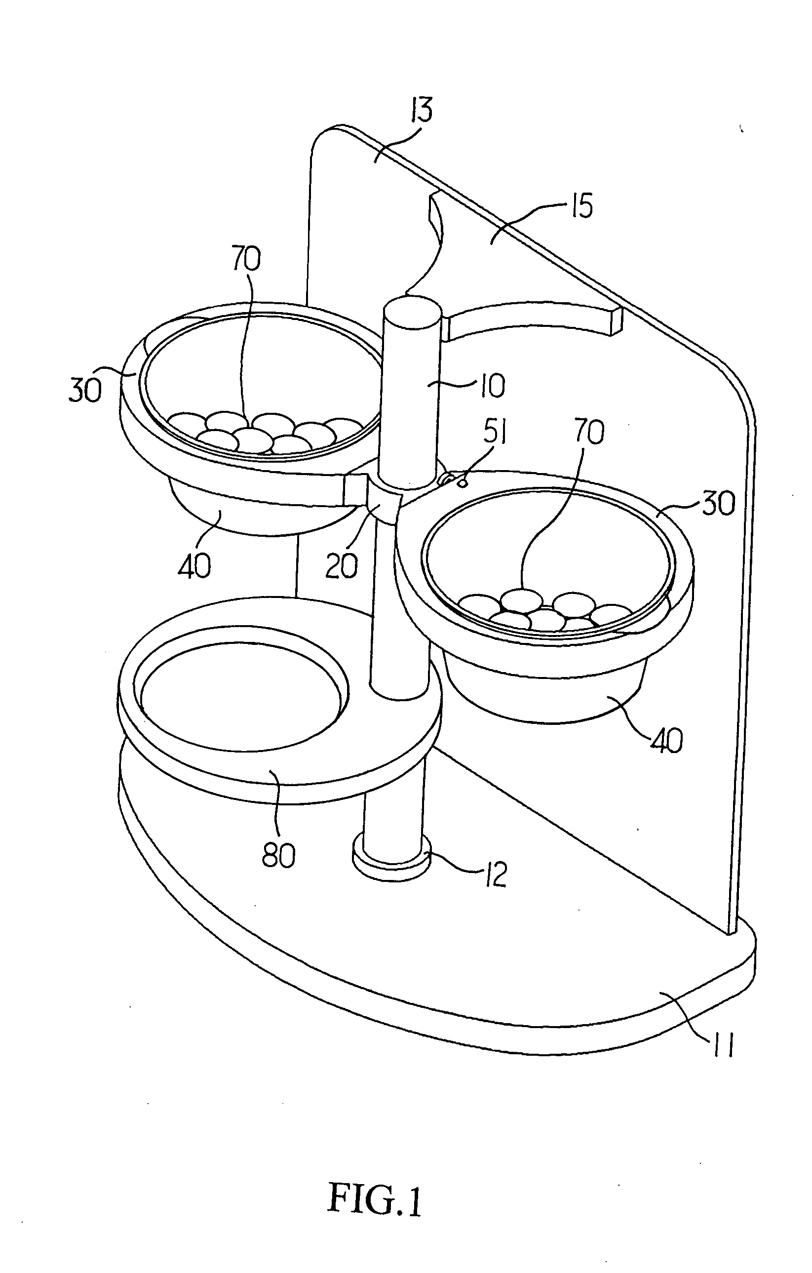
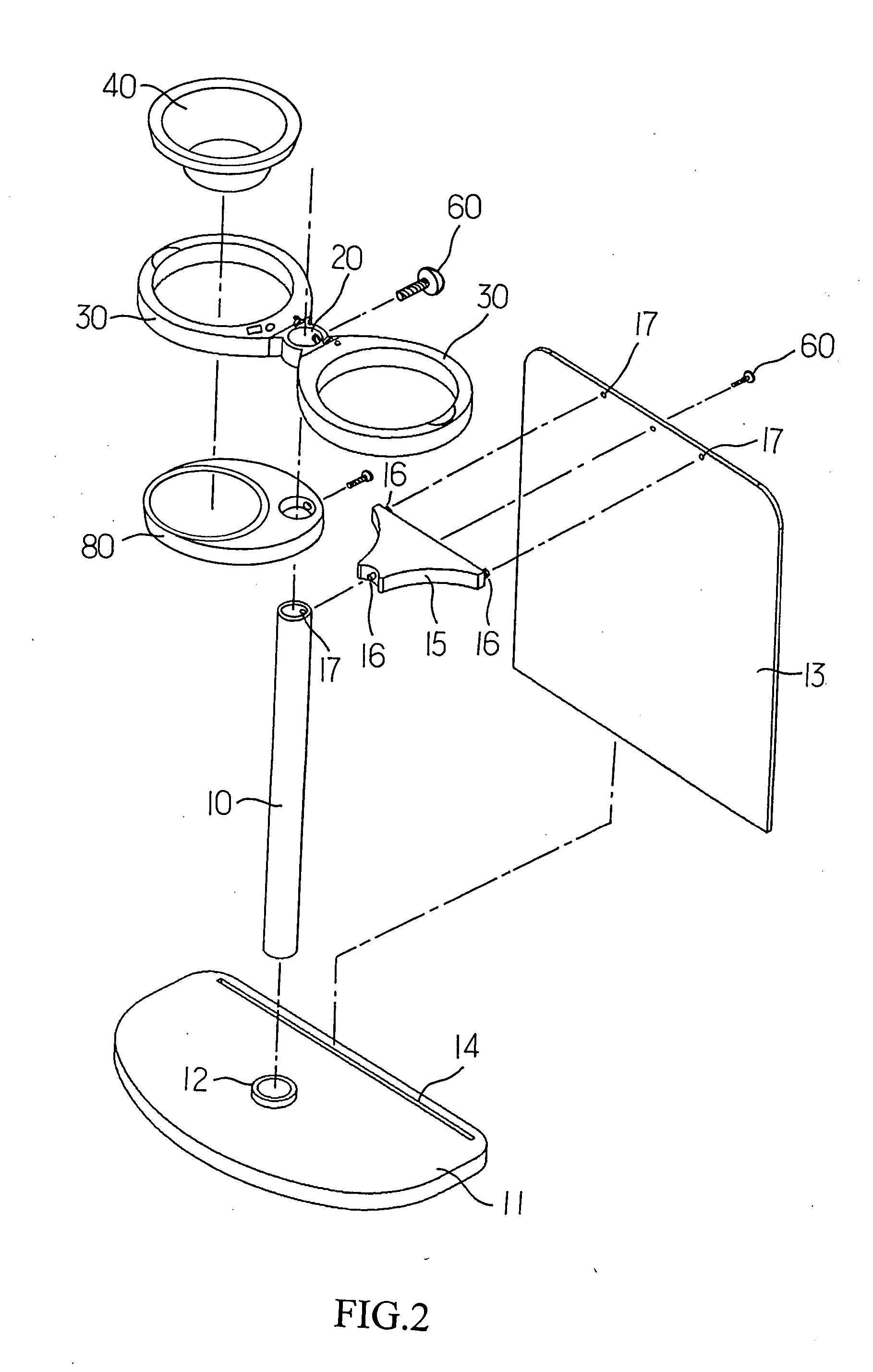
[0021] To make it easier for the examiner to understand the structure, and overall operation of this invention, the specification accompanied by the drawings is described as follows. Please refer to FIGS. 1 and 2. The pet food feeder of this invention comprises:

[0022] a support rod 10, being the main structure of the entire pet food feeder, and in this embodiment as shown in the figures, the support rod 10 at its bottom having a bottom plate 11, for placing the entire pet food feeder on the floor by the bottom plate 11, wherein the plate of the bottom plate 11 has a hole 12 for accommodating the insertion of the support rod 10, and the bottom plate at one side has a rear panel 13, and the bottom of the rear panel 13 is inserted into the insert groove 14 of the bottom plate 11, and the top of the support rod 10 has a connecting member 15 coupled with the rear panel 13; the connecting member 15 and support rod 10 are coupled with the rear panel 13 by the connection of a latch 16 and ...


PUM


Abstract

The present invention discloses a pet food feeder, comprising a connecting member coupled to a support rod, a first connecting surface vertically disposed on the connecting member, a second connecting surface vertically disposed on a containing member of a food bin, a pivotal axis and an axial hole respectively disposed on the first and second connecting surfaces respectively, such that the entire pet food feeder passing through the pivotal axis and the axial hole to combine the containing member and the support rod, and a positioning latch on the second connecting surface being extended into a fixing hole on the first connecting surface to fix an angle of elevation for the opening of the food bin. The positioning latch can be extended into other fixing hole to adjust the angle of elevation of the opening of the food bin to collect the food towards the utmost bottom of the food bin and facilitate the feeding of pets.

Description

BACKGROUND OF THE INVENTION [0001] 1. Field of the Invention [0002] The present invention relates to a pet food feeder, more particularly to a pet food feeder comprising a connecting member coupled to a support rod, a first connecting surface vertically disposed on the connecting member, a second connecting surface vertically disposed on a containing member of a food bin, a pivotal axis and an axial hole respectively disposed on the first and second connecting surfaces respectively, such that the entire pet food feeder passing through the pivotal axis and the axial hole to combine the containing member and the support rod, and a positioning latch on the second connecting surface being extended into a fixing hole on the first connecting surface to fix an angle of elevation for the opening of the food bin. The positioning latch can be extended into other fixing hole to adjust the angle of elevation of the opening of the food bin to collect the food towards the utmost bottom of the foo...

Claims


Application Information

Patent Timeline
IPC IPC(8): A01K5/01
CPCA01K5/0114
Inventor HAMMER, MARKUS
Owner HAMMER MARKUS
Why Eureka
Try Eureka