Motor drive for a patio umbrella

a motor drive and umbrella technology, applied in the field of umbrellas, can solve the problems of time-consuming and serious bearer

Inactive Publication Date: 2005-04-07
VIVIAN CHARLIE +1
View PDF7 Cites 53 Cited by
  • Summary
  • Abstract
  • Description
  • Claims
  • Application Information

AI Technical Summary

Benefits of technology

[0020] It is an object of the invention to provide improved elements and arrangements thereof for the purp

Problems solved by technology

In a setting where many umbrellas are used, and particularly in a commercial setting such as an outdoor cafe or an outdoor resort, it can be a time consuming task to open the umbrellas at the s

Method used


Image

  • Motor drive for a patio umbrella
  • Motor drive for a patio umbrella
  • Motor drive for a patio umbrella

Examples


first embodiment

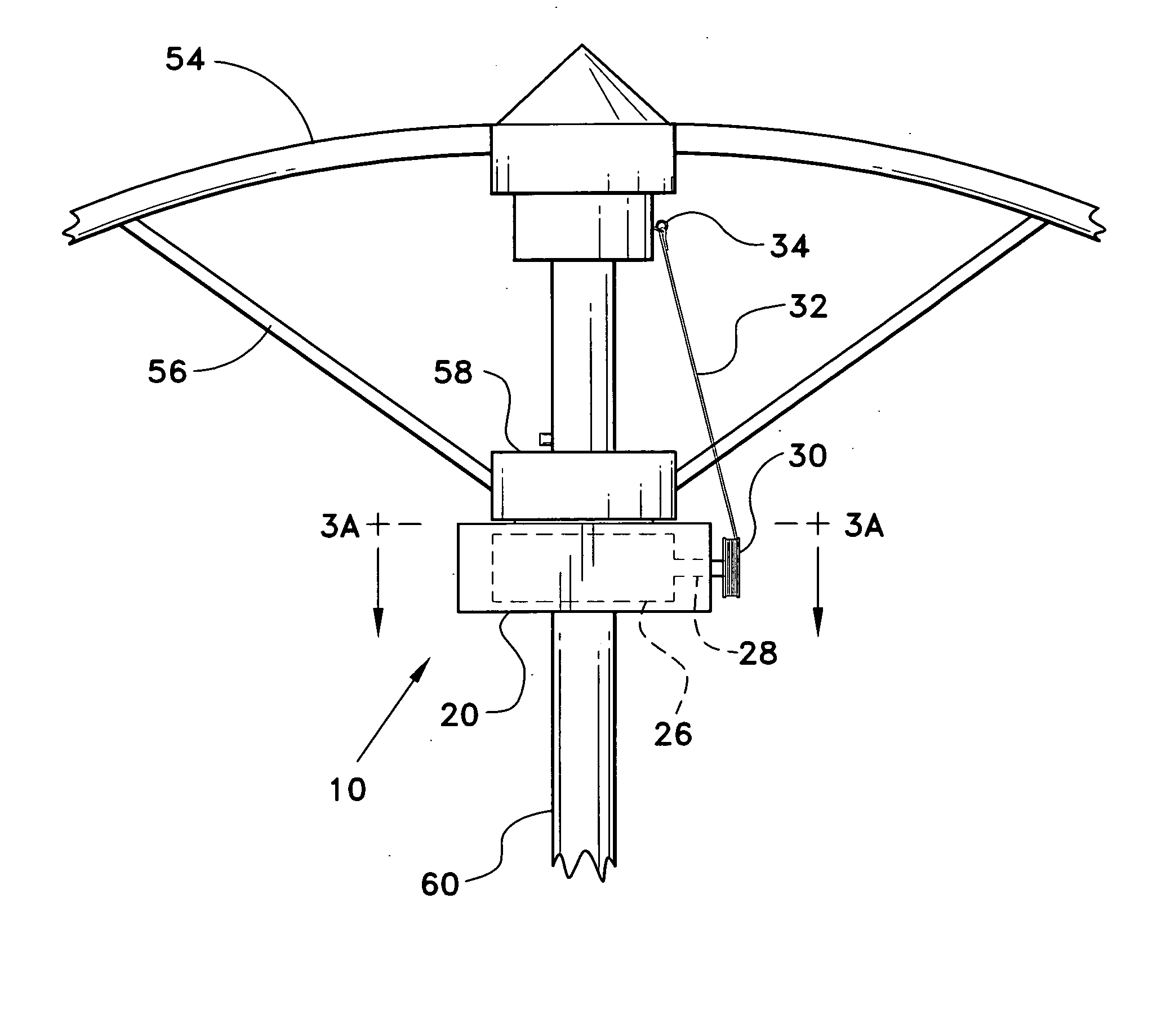
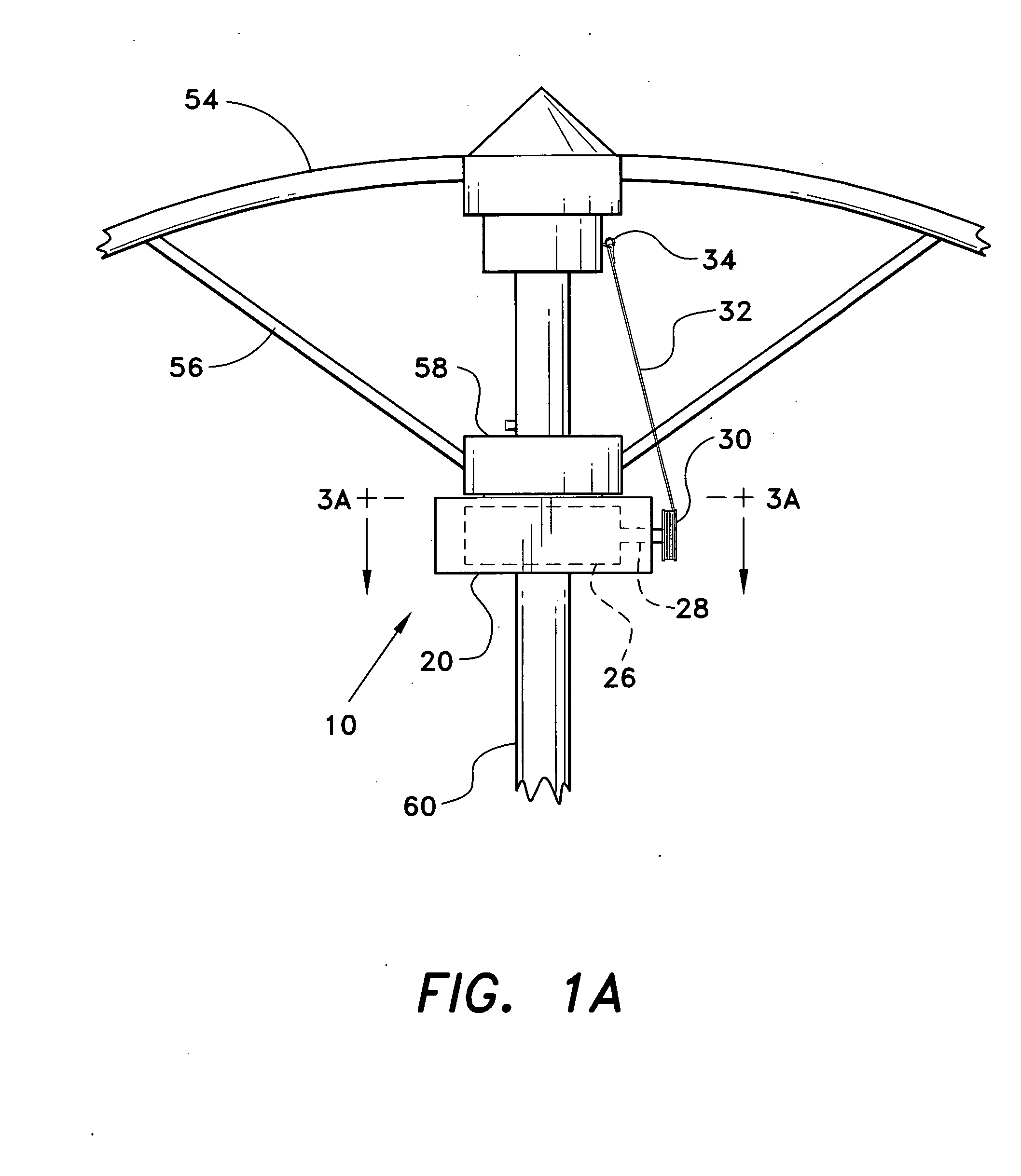
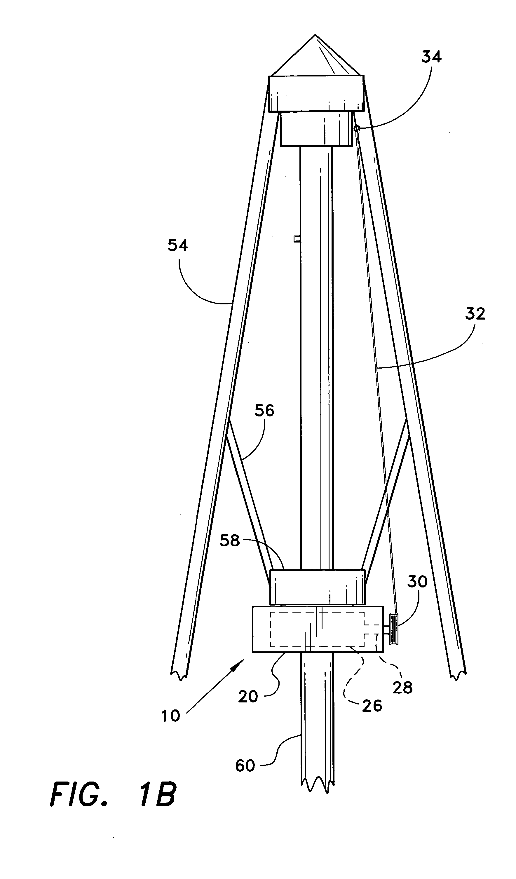
[0035] Turning now to FIG. 3A, the motor drive for a patio umbrella 10 is shown in greater detail. The housing 20 is comprised of a first half 22 and a second half 24. A means for mounting the housing 20 to the umbrella 10 comprises a semi-circular recess 64 formed in each of the housing halves 22, 24 so that the halves 22, 24 may be joined together around a portion of the umbrella 10. As illustrated in FIG. 3A, the housing 20 is mounted to the umbrella hub 58 by joining the halves 22, 24 together, the hub 58 being clamped snugly between the halves 22, 24. The motor 26 is disposed within the first half 22, while batteries 48 are disposed in the second half 24. Shaft 28 extends from the motor 26, extending to the outside of the first half 22 of the housing 20. Spool 30 is disposed on the end of the shaft 28, with a length of cord 32 attached to the spool 30.

second embodiment

[0036] In a second embodiment shown in FIG. 3B, a single or unitary housing 20 contains both the motor 26 and the batteries 48. A means for mounting the unitary housing 20 to the umbrella 10 comprises a semi-circular recess 64 formed in the side of the housing 20, and a semi-circular clamping member 62 used to clamp the housing 20 about a part of the umbrella 10. As illustrated in FIG. 3B, the unitary housing 20 is mounted to the umbrella hub 58.

[0037] In either embodiment, a series of reduction gears may be included, installed within the housing 20 or contained within the motor 26 itself, to increase the torque available to open the umbrella. Referring to FIG. 4, the embodiment of FIG. 3A is illustrated with reduction gears 29 and 129. Gear 29 is disposed on the motor shaft 28. Gear 129 drives a separate shaft 128 that, in turn, drives the spool 30. It can be recognized that additional reduction gearing configurations may be employed, including worm or crown gear configurations, or...


PUM


Abstract

The motor drive for a patio umbrella is a motorized accessory for raising and lowering a patio umbrella. The motor drive for a patio umbrella has an electric motor contained within a housing mounted to the sliding hub, or to the pole, of a patio umbrella. A spool is fixed on the motor's shaft, and a thin cord is taken up by, or unwound from, the spool as the motor is operated in forward or reverse directions. The cord is fastened to the patio umbrella so that, as the cord is taken up by the spool, the umbrella opens. As the cord unwinds from the spool, the umbrella closes. A control circuit operates the motor automatically in response to a photosensor or a remote control signal, or manually by a simple three-position switch.

Description

CROSS-REFERENCE TO RELATED APPLICATION [0001] This application claims the benefit of U.S. Provisional Patent Application Ser. No. 60 / 507,958, filed Oct. 3, 2003.BACKGROUND OF THE INVENTION [0002] 1. Field of the Invention [0003] The present invention relates to umbrellas and, more particularly, to a motor drive for a patio umbrella that can be installed on conventional, manually operated, patio-type umbrellas so that the umbrella may be opened and closed automatically. [0004] 2. Description of the Related Art [0005] Patio umbrellas color the landscape of countless places, urban and rural. From sidewalk cafes to beach resorts, alongside swimming pools, and on backyard patios, these umbrellas are used to provide a sun shade, protection from rain, and decoration. [0006] A typical patio umbrella includes a canopy that is supported atop an umbrella pole by a number of staves, the staves being further supported by stave supports that, coupled to a sliding hub, are used to open and close t...

Claims


Application Information

Patent Timeline
IPC IPC(8): A45B25/16
CPCA45B25/16
Inventor VIVIAN, CHARLIECRESSWELL, KEVIN R.
Owner VIVIAN CHARLIE
Why Eureka
Try Eureka