Article-orienting conveyor

a conveyor and article technology, applied in the direction of conveyor parts, rollers, transportation and packaging, etc., can solve the problem of not being able to ensure the orientation of articles

Inactive Publication Date: 2005-04-07
LAITRAM LLC
View PDF17 Cites 64 Cited by
  • Summary
  • Abstract
  • Description
  • Claims
  • Application Information

AI Technical Summary

Benefits of technology

[0003] This need and other needs are satisfied by a conveyor embodying features of the invention. In one aspect, the conveyor comprises a first conveyor belt and a second belt. The first conveyor belt runs along a conveying path at a first velocity in a conveyance direction. The first conveyor belt extends transverse to the conveyance direction from a first side to a second side. The first conveyor belt includes a plurality of article-supporting rollers arranged to direct supported articles toward the first side as the first conveyor belt runs in the conveyance direction. The second belt is disposed proximate the second side of the first conveyor belt. The second belt runs at a second velocity parallel to the first conveyor belt. The first velocity (of the first conveyor belt) in the conveyance direction exceeds the second velocity (of the second belt) in the conveyance direction. The difference between the velocities causes articles on the first conveyor belt extending past its second side and into contact with the second belt to rotate.

Problems solved by technology

But it is often not possible to ensure that articles will be placed on a conveyor in the desired alignment and orientation.

Method used


Image

  • Article-orienting conveyor
  • Article-orienting conveyor
  • Article-orienting conveyor

Examples


Embodiment Construction

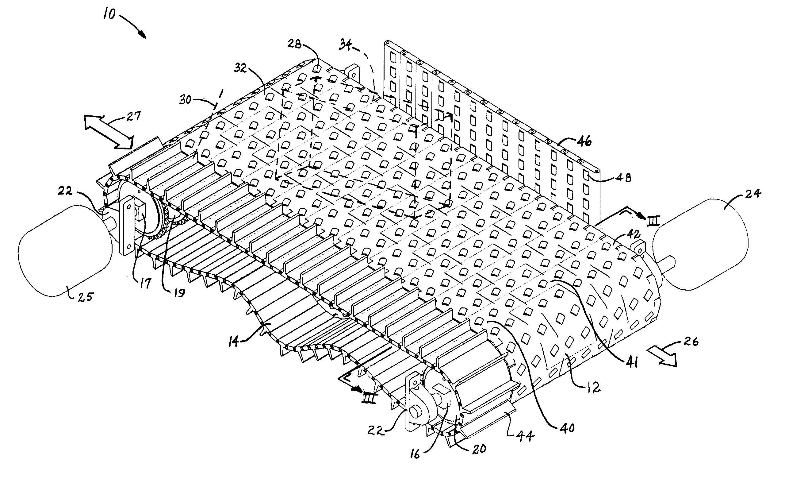
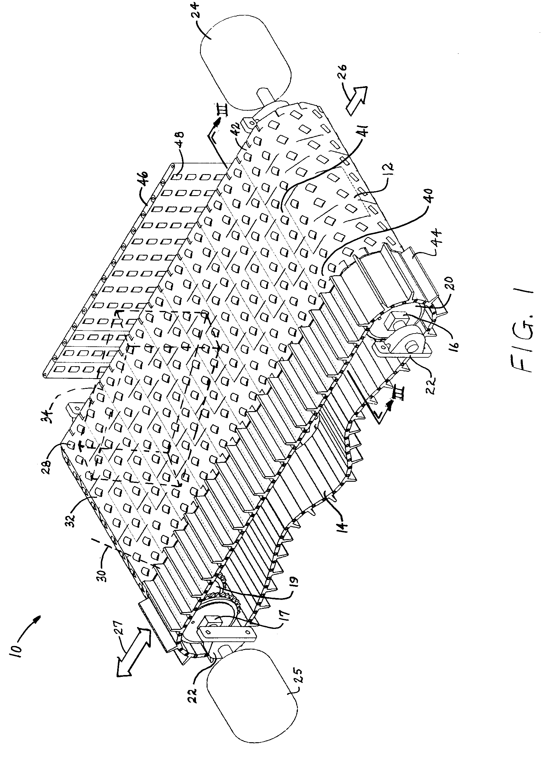
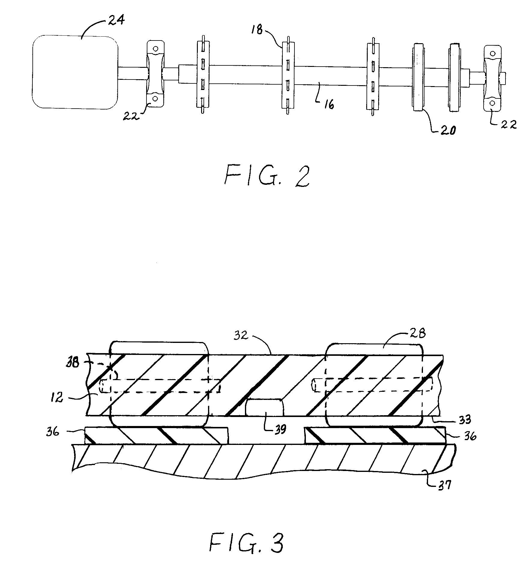
[0016] An orientation and registration conveyor embodying features of the invention is shown in FIG. 1. The conveyor 10 includes two belts: a conveyor belt 12 and an orientation belt 14. The substantially coplanar belts are looped between a pair of shafts 16, 17. One of the shafts 16 serves as a drive shaft for the conveyor belt 12 and includes a set of toothed drive sprockets 18 mounted on the shaft, as shown in FIG. 4. The drive shaft for the conveyor belt also includes a set of idler rollers 20 around which the orientation belt 14 slides. The shaft 16 is supported at its ends by bearing blocks 22 mounted to a conveyor frame (not shown for simplicity). A first drive motor 24 coupled to the shaft 16 drives the conveyor belt 12 in a conveyance direction 26. The other shaft 17 serves as a drive shaft for the orientation belt 14. Toothed drive sprockets 19 for the orientation belt are mounted on the shaft to drivingly engage drive structure on the inner side of the orientation belt. I...


PUM


Abstract

A conveyor for orienting and registering articles in a preferred orientation and position for accurate downstream processing. The conveyor includes a conveyor belt running in a conveyance direction next to an orientation belt running parallel in an opposite direction or more slowly in the same direction. The orientation belt has upstanding structure, such as flights, or a high-friction surface. The conveyor belt includes article-supporting rollers on a top side. The rollers are arranged to rotate about axes oblique to the conveyance direction. The rollers also extend below the bottom side of the belt and are rotated by dynamic contact with bearing surfaces supporting the belt as it advances in the conveying direction. The rotating rollers direct conveyed articles toward a side rail. If a portion of a conveyed article extends past the side edge of the conveyor belt into the path of the orientation belt, the obstructions or high-friction surface of the slower- or oppositely-moving orientation belt strikes the conveyed articles and cause them to rotate clockwise toward an alignment of the article in the conveyance direction and into registration against the side rail at the downstream end of the conveyor. In other versions of the article-orienting conveyor, the orientation belt is replaced by a row of posts or a rotating paddle wheel that strikes conveyed articles extending past the side edge of the conveyor belt.

Description

BACKGROUND OF INVENTION [0001] The invention relates generally to power-driven conveyors and, more particularly, to an orientation and registration conveyor using a roller-top conveyor belt. [0002] Many conveying applications require that conveyed articles be aligned single file in a specific orientation for downstream processing or inspection. But it is often not possible to ensure that articles will be placed on a conveyor in the desired alignment and orientation. Consequently, there is a need for a conveyor that can align and orient conveyed articles in spite of their original orientations on the conveyor. SUMMARY OF INVENTION [0003] This need and other needs are satisfied by a conveyor embodying features of the invention. In one aspect, the conveyor comprises a first conveyor belt and a second belt. The first conveyor belt runs along a conveying path at a first velocity in a conveyance direction. The first conveyor belt extends transverse to the conveyance direction from a first...

Claims


Application Information

Patent Timeline
Patent Type & Authority Applications(United States)
IPC IPC(8): B65G17/24B65G47/244
CPCB65G47/2445B65G17/24
Inventor COSTANZO, MARK
Owner LAITRAM LLC
Why Eureka
Try Eureka