
Inline water filter

a water filter and inline technology, applied in the field of inline filters, can solve the problems of unfavorable homeowner removal or replacement, unfavorable homeowner installation and replacement, and inconvenient installation and replacement, and achieve the effects of convenient and reliable items, simple and compact structure, and convenient and reliable items

Inactive Publication Date: 2005-04-07
SWANSON PHILLIP A
View PDF16 Cites 18 Cited by
  • Summary
  • Abstract
  • Description
  • Claims
  • Application Information

AI Technical Summary

Benefits of technology

[0019] It is another object of the present invention to provide a inline water filter which is simple, compact and inexpensive, yet is a convenient and reliable item.
[0020] It is an additional object of the present invention to provide an inline water filter which is easily installed and replaced as a single, self-contained unit and functions as a connecting supply line between a water pipe and a faucet or toilet and which can be made in a variety of sizes and configurations.
[0021] It is an further object of the present invention to provide an inline water filter which is easily constructed from common or standard plumbing items.
[0023] In another embodiment of the invention, the inline filter has small diameter inlet and outlet connecting tubes and a larger diameter filter body. The connecting fittings have a large diameter proximal portion for insertion into the filter body and a small diameter distal stem portion for insertion into the connecting tubes. The passageways defined through the fittings have a small opening at the distal stem portion and a large opening at the proximal end allowing for a large surface area to reduce clogging at the ends of the filter media.

Problems solved by technology

However, most filters in the prior art are rigid and are connected to the water supply by rigid piping which is cut, fitted, threaded, flared, or otherwise adapted to existing plumbing.
Such systems and processes are not inexpensive as they involve unnecessary costs both in materials and installation.
Further, they cannot easily be removed or replaced by a typical homeowner.
However, because of their placement, these filters are limited in size and often are generally obtrusive to using the faucet.
Also, they do not provide protection for washers or o-ring seals.

Method used


Image

  • Inline water filter
  • Inline water filter
  • Inline water filter

Examples


first embodiment

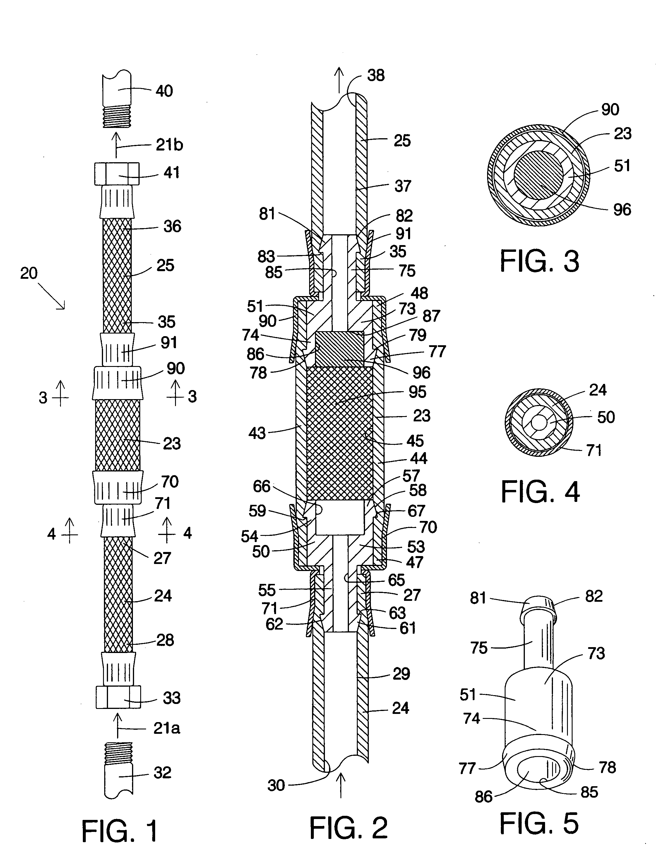
[0038] Referring to the drawings, particularly FIGS. 1 through 5, an inline water filter, generally designated 20, for filtering water flowing in the direction indicated by the arrows 21a and 21b is seen to include a filter body 23, an inlet tube 24 and an outlet tube 25.

[0039] The elongate flexible connecting inlet tube 24 has a proximal end 27 and a distal end 28 and a side wall 29 defining a longitudinal flow passage 30 therebetween. The inlet tube 24 has a female connector at its distal end adapted for attachment to an upstream source of fluid indicated by the externally threaded pipe 32 by means of a hex nut 33 or other connecting means.

[0040] The elongate flexible connecting outlet tube 25 has a proximal end 35 and a distal end 36 and a side wall 37 defining a longitudinal flow passage 38 therebetween. The outlet tube 25 has a female connector at its distal end adapted for attachment to a downstream fluid delivery point or system indicated by an externally threaded pipe 40 by...

second embodiment

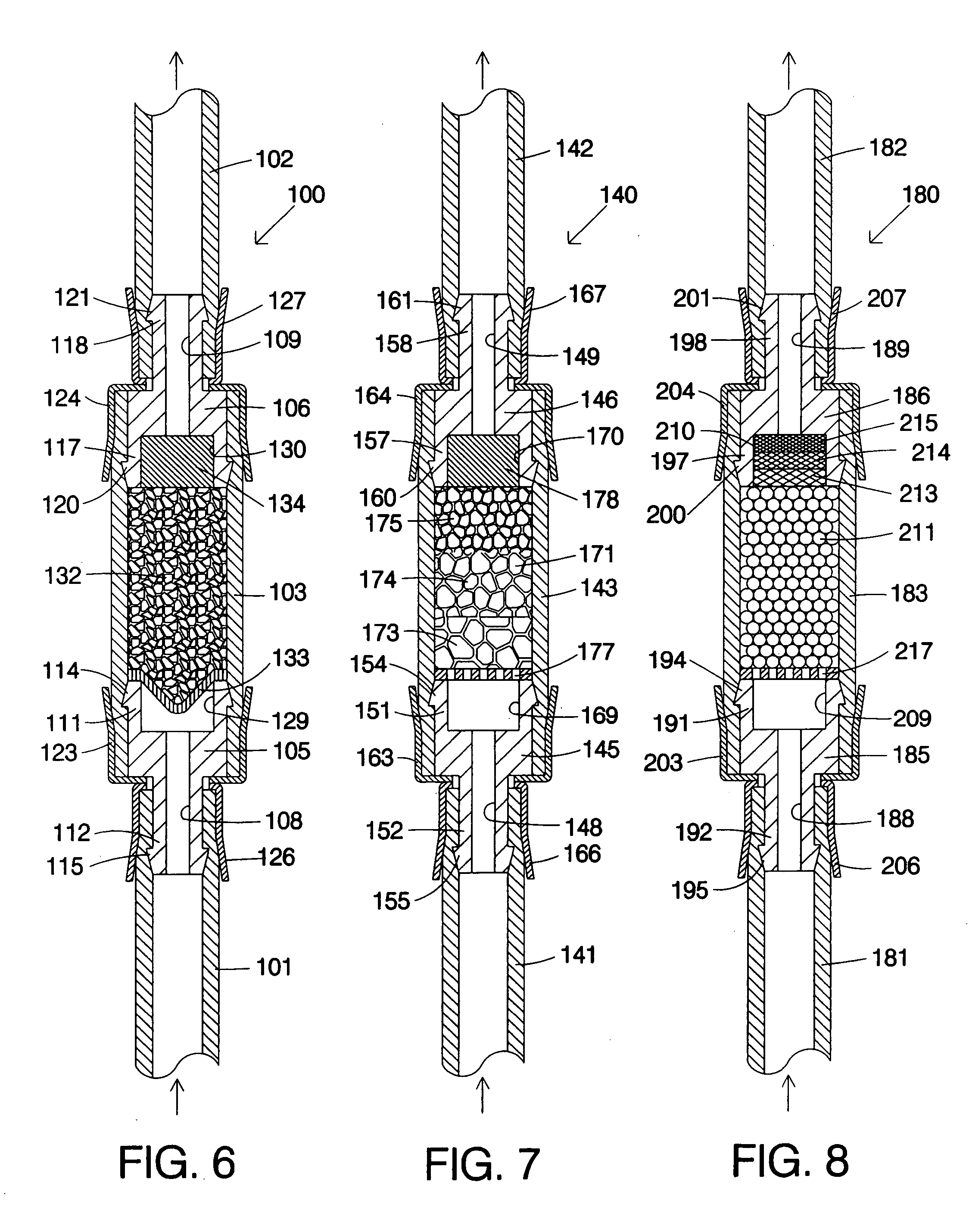
[0050] Referring to FIG. 6, the invention is shown. The inline filter, generally designated 100, includes elongate flexible inlet and outlet connecting tubes 101 and 102 defining respective fluid passageways and an intermediate flexible hollow filter body 103 joined together by a pair of dual-diameter connecting fittings 105 and 106 each defining flow passageways 108 and 109, respectively, therethrough. The inlet connecting fitting 105 has respective proximal and distal ends 111 and 112 with external cammed circumferential barbs 114 and 115, respectively. The outlet connecting fitting 106 has proximal and distal ends 117 and 118 with external circumferential cammed barbs 120 and 121, respectively. The ends of the filter body 103 are affixed to the fittings 105 and 106 by crimped ferrules 123 and 124 and the proximal ends of the inlet and outlet tubes 101 and 102 are affixed to the respective fittings 105 and 106 by crimped ferrules 126 and 127, respectively. The inlet and outlet tub...

third embodiment

[0053] Referring to FIG. 7, the invention is shown. The inline filter, generally designated 140, includes elongate flexible inlet and outlet connecting tubes 141 and 142 defining respective fluid passageways and an intermediate flexible hollow filter body 143 joined together by a pair of dual-diameter connecting fittings 145 and 146 each defining flow passageways 148 and 149, respectively, therethrough. The inlet connecting fitting 145 has respective proximal and distal ends 151 and 152 with external cammed circumferential barbs 154 and 155, respectively. The outlet connecting fitting 146 has proximal and distal ends 157 and 158 with external circumferential cammed barbs 160 and 161, respectively. The ends of the filter body 143 are affixed to the fittings 145 and 146 by crimped ferrules 163 and 164 and the proximal ends of the inlet and outlet tubes 141 and 142 are affixed to the respective fittings 145 and 146 by crimped ferrules 166 and 167, respectively. The inlet and outlet fit...


PUM

PropertyMeasurementUnit
Diameteraaaaaaaaaa
Sizeaaaaaaaaaa
Flexibilityaaaaaaaaaa

Abstract

An inline water filter includes flexible inlet and outlet connecting tubes and an intermediate filter body joined together by a pair of dual-diameter connecting fittings defining a flow passageway therethrough. Filter media is disposed within the filter body and within enlarged sections of the fittings. The connecting tubes are held onto the barbed fittings by ferrules crimped thereover and have connectors at their free ends for attachment to a fluid source and a fluid delivery point.

Description

CROSS-REFERENCE TO RELATED APPLICATIONS [0001] This application claims the benefit of Provisional Patent Application Ser. No. 60 / 455,678, filed Mar. 19, 2003.BACKGROUND OF THE INVENTION [0002] 1. Technical Field [0003] This invention relates generally to an inline filter and, more particularly, to an inline filter adapted for use along a water supply line. [0004] 2. Background Art [0005] In the prior art, water filters are well-known. Water filters can be employed to physically remove solid matter or suspended impurities, such as particulate or sediment. Filters can also be employed to chemically remove dissolved materials or impurities and remove bad tastes or smells. Filters can also be designed to remove biological agents to minimize disease. [0006] Also well-known are flexible supply lines which provide a final connection between conventional house plumbing and a faucet. However, most filters in the prior art are rigid and are connected to the water supply by rigid piping which ...

Claims


Application Information

Patent Timeline
IPC IPC(8): B01D27/02B01D35/02
CPCB01D27/02B01D35/02B01D27/08
Inventor SWANSON, PHILLIP A.
Owner SWANSON PHILLIP A
Learn More