Electronic component mounting apparatus and electronic component mounting method

a technology for mounting apparatuses and electronic components, applied in the direction of soldering apparatuses, manufacturing tools,auxillary welding devices, etc., can solve the problems of shortening the tact time of mounting operation, unable to reduce the amount of mounting head required in the mounting operation, and achieving better mounting positional precision

Inactive Publication Date: 2005-04-07
PANASONIC CORP
View PDF3 Cites 6 Cited by
  • Summary
  • Abstract
  • Description
  • Claims
  • Application Information

AI Technical Summary

Benefits of technology

[0014] In accordance with the present invention, in such an electronic component mounting operation that the electronic components are sucked/held by the respective plurality nozzles provided on the mounting head and are mounted on the electronic component mounting portions of the board 9, such a relative position detecting operation is carried out with respect to all of the electronic components which have been sucked/held by the nozzles, while in this relative position detecting operation, both the provisionally positioned electronic component and the electronic component mounting portion are ob

Problems solved by technology

However, in the above-described prior art, since there is such a restriction that the camera must be positioned between the board and the mounting head, a limitation is made in shortening of tact time of the mounting

Method used


Image

  • Electronic component mounting apparatus and electronic component mounting method
  • Electronic component mounting apparatus and electronic component mounting method
  • Electronic component mounting apparatus and electronic component mounting method

Examples


embodiment 1

[0040] (Embodiment 1)

[0041] In the patent specification of the present invention, it is so considered that a carrier member (carrier jig) to which a plurality of piece boards have been set is also a “board”. In this case, it is so assumed that a mounting unit of an electronic component, which has been formed on a piece board set to the carrier member corresponds to “electronic component mounting portion which has been formed on board”.

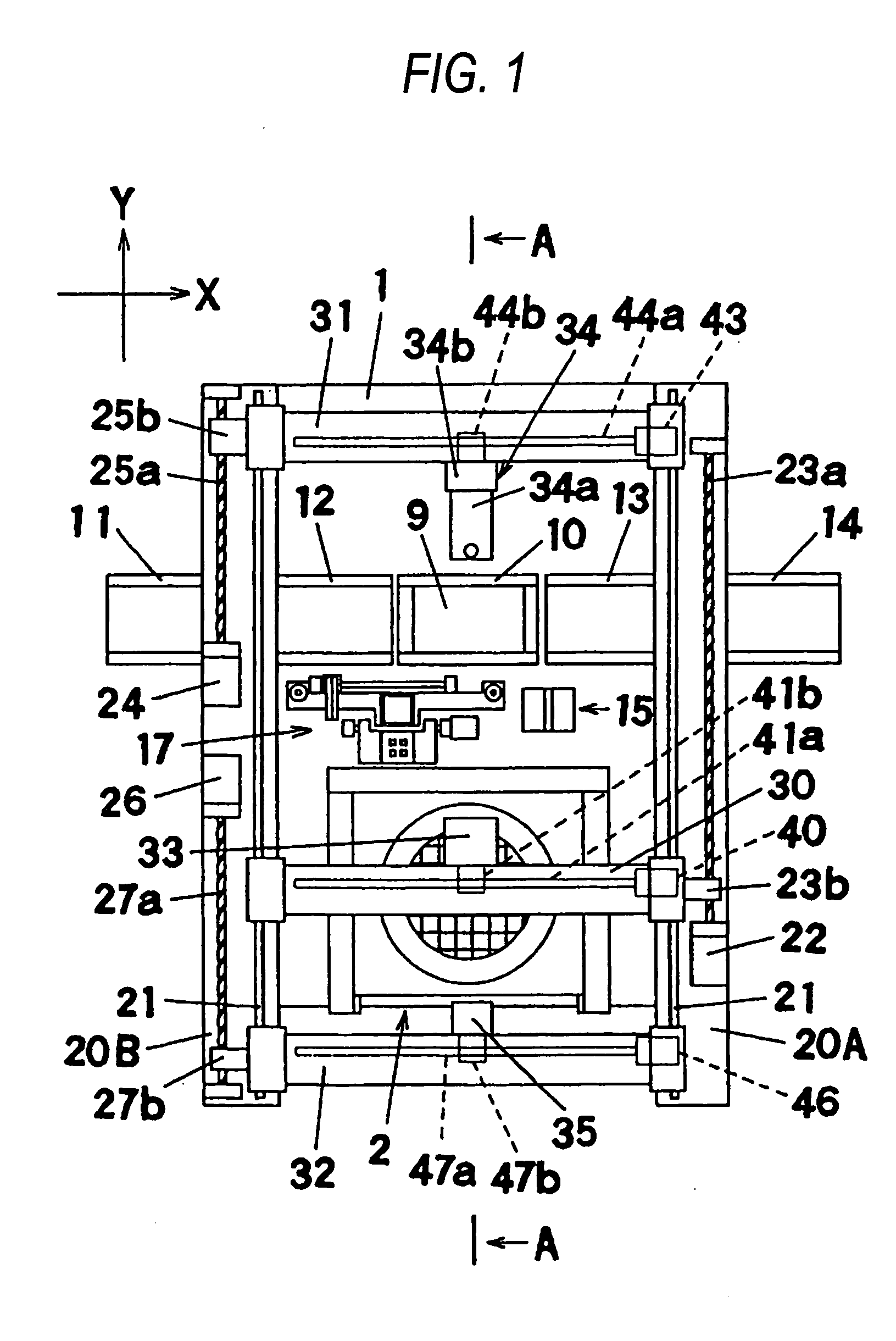
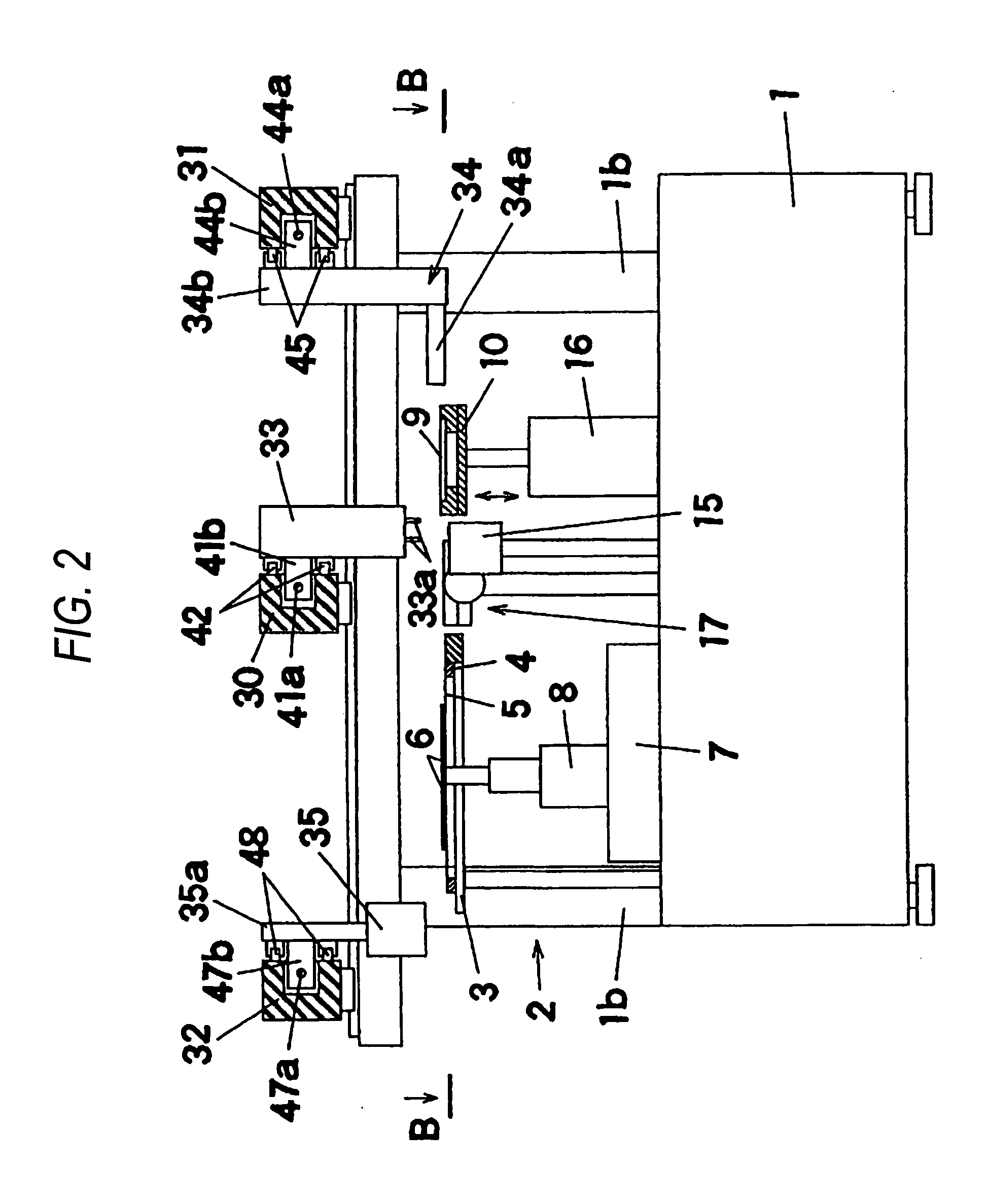
[0042] First, an entire structure of an electronic component mounting apparatus will now be explained with reference to FIG. 1, FIG. 2, and FIG. 3. FIG. 2 is a sectional view for showing the electronic component mounting apparatus, taken along an arrow “A-A” of FIG. 1. FIG. 3 is another sectional view for indicating the electronic component mounting apparatus, taken along an arrow “B-B” of FIG. 2. In FIG. 1, an electronic component supplying unit 2 is arranged on a base 1. As shown in FIG. 2 and FIG. 3, the electronic component supplying unit 2 is equ...

embodiment 2

[0144] (Embodiment 2)

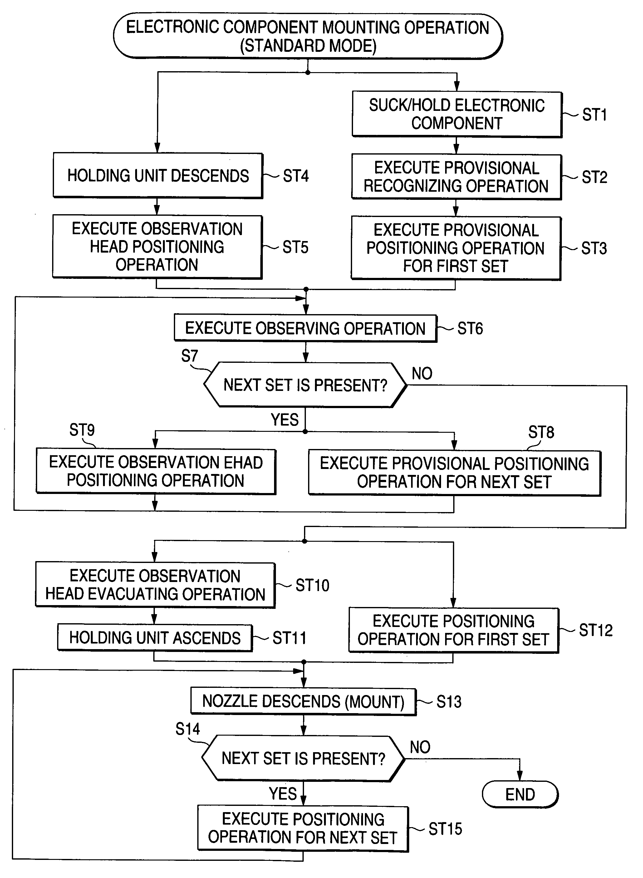
[0145] Next, a description is made of an electronic component mounting apparatus according to an embodiment 2 of the present invention. As to the electronic component mounting apparatus of the embodiment 2, only a processing mechanism operated in a standard mode is different from that of the embodiment 1, and other arrangements and processing functions in both a high precision mode and a high speed mode are identical to those of the embodiment 1. Accordingly, the explanation as to the electronic component mounting apparatus according to the embodiment mode 2 is limited to a processing function executed in the standard mode.

[0146]FIG. 25 is a functional block diagram for indicating the processing function in the case that the electronic component mounting apparatus according to the embodiment 2 of the present invention is operated in the standard mode. In the embodiment 1 (see FIG. 10), both the provisional positioning positional information of the mounting head...


PUM

PropertyMeasurementUnit
Optical propertiesaaaaaaaaaa

Abstract

In an electronic component mounting method in which electronic components are sucked/held by plural respective nozzles provided on a mounting head so as to be mounted on electronic component mounting portions of a board, such a mounting operation is sequentially carried out as to all of the electronic components, in which the electronic components are sucked/held by the plural nozzles; an electronic component sucked/held by one of the plural nozzles is provisionally positioned above one electronic component mounting portion; both this electronic component and the electronic component mounting portion are observed by an observation head which is located between the board and the mounting head; a relative position detecting operation for detecting a relative positional relationship between this electronic component and the electronic component mounting portion is carried out as to all of the electronic components held by the mounting head; and the electronic component is positioned with respect to the electronic component mounting portion so as to be mounted thereon while the detected relative positional relationship is reflected.

Description

BACKGROUND OF THE INVENTION [0001] The present invention is related to an electronic component mounting apparatus and an electronic component mounting method, which mount an electronic component on a board. [0002] In electronic component mounting apparatus, mounting operations are repeatedly carried out in which electronic components derived from electronic component supply units are held by mounting heads and then are mounted on boards. In these mounting operations, since the electronic components are required to be positioned on the boards in higher precision, such positioning methods have been widely employed. In the positioning methods, while both the electronic components being held by the mounting heads and positions of mounting points on the boards are optically detected, the electronic components and the boards are relatively positioned with each other based upon position detecting results. [0003] In such an optical position detecting operation, two images acquired by photog...

Claims


Application Information

Patent Timeline
IPC IPC(8): H05K13/04H05K13/08
CPCY10T29/49131H05K13/0413H01L24/75H01L24/81H05K13/0812H01L2224/7598H05K13/04
Inventor HAJI, HIROSHI
Owner PANASONIC CORP
Why Eureka
Try Eureka