Combustion chamber subassembly for a heating device, particularly a vehicle heating device

a heating device and combustion chamber technology, applied in the direction of combustion process, combustion type, burner, etc., can solve the problems of increased exhaust gas emission, failure of the combustion chamber, and impaired fuel introduction into the porous evaporator medium, so as to improve the starting behavior

Inactive Publication Date: 2007-06-12
J EBERSPAECHER GMBH & CO KG
View PDF16 Cites 5 Cited by
  • Summary
  • Abstract
  • Description
  • Claims
  • Application Information

AI Technical Summary

Benefits of technology

[0007]The fuel is thus not delivered directly from the fuel supply toward the combustion chamber, but instead there is a pre-distribution, which results in an evening out of the fuel introduction into the combustion chamber and thus a markedly improved independence on the mounting position. For example, it can be provided that a groove-like recess is formed for forming the fuel distribution channel arrangement in the housing wall.
[0011]To provide for a good mixing with combustion air of the evaporated fuel delivered into the combustion chamber, at least one combustion air inlet aperture is formed at a region of the peripheral wall not covered by the fuel distribution element.
[0012]To further the evaporation of the fuel, which in particular improves the starting behavior at low environmental temperatures, the fuel distribution element forms or contains at least a portion of a heating arrangement.

Problems solved by technology

In evaporative burners, in which the fuel is delivered into a combustion chamber via a porous medium, the problem exists that the introduction of the fuel into this porous evaporator medium can be impaired by changing the mounting position, since the fuel is generally distributed by gravity before introduction and after introduction into this porous medium.
A very non-uniform distribution leads to a correspondingly non-uniform evaporation of fuel in the combustion chamber, which can have the consequences that the combustion taking place in the combustion chamber leads to an increased exhaust gas emission, that the starting process of such a combustion chamber is impaired, and that excessive accumulation of combustion residues in the combustion chamber occurs, which in extreme cases can lead to failure of the combustion chamber.

Method used


Image

  • Combustion chamber subassembly for a heating device, particularly a vehicle heating device
  • Combustion chamber subassembly for a heating device, particularly a vehicle heating device

Examples


Embodiment Construction

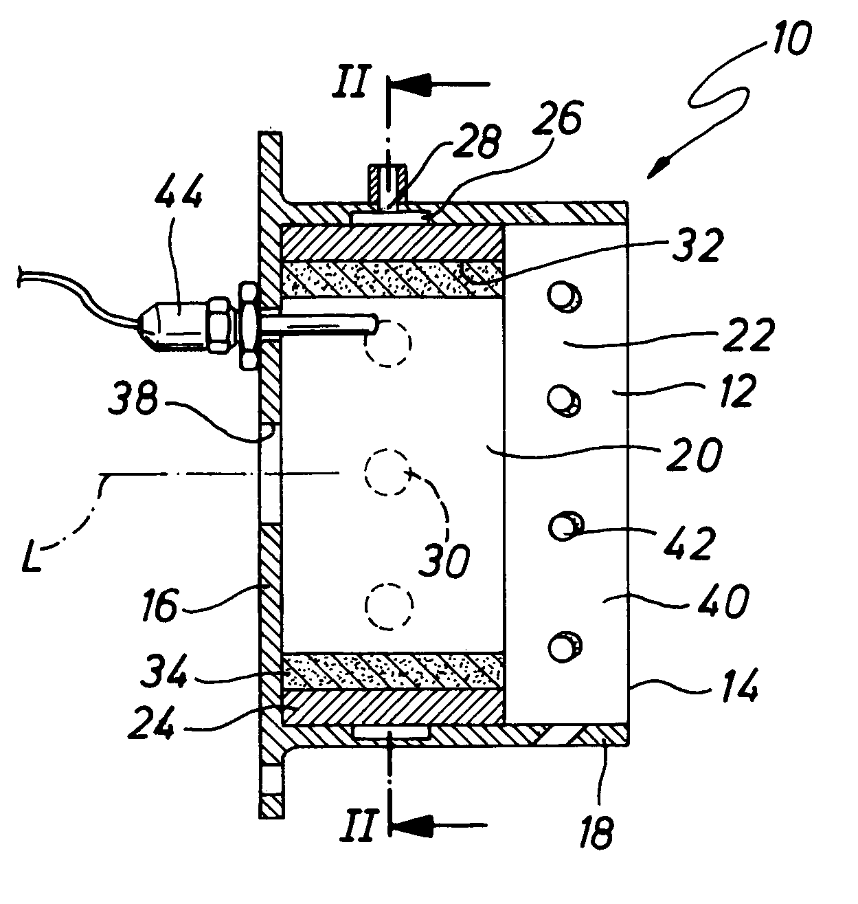
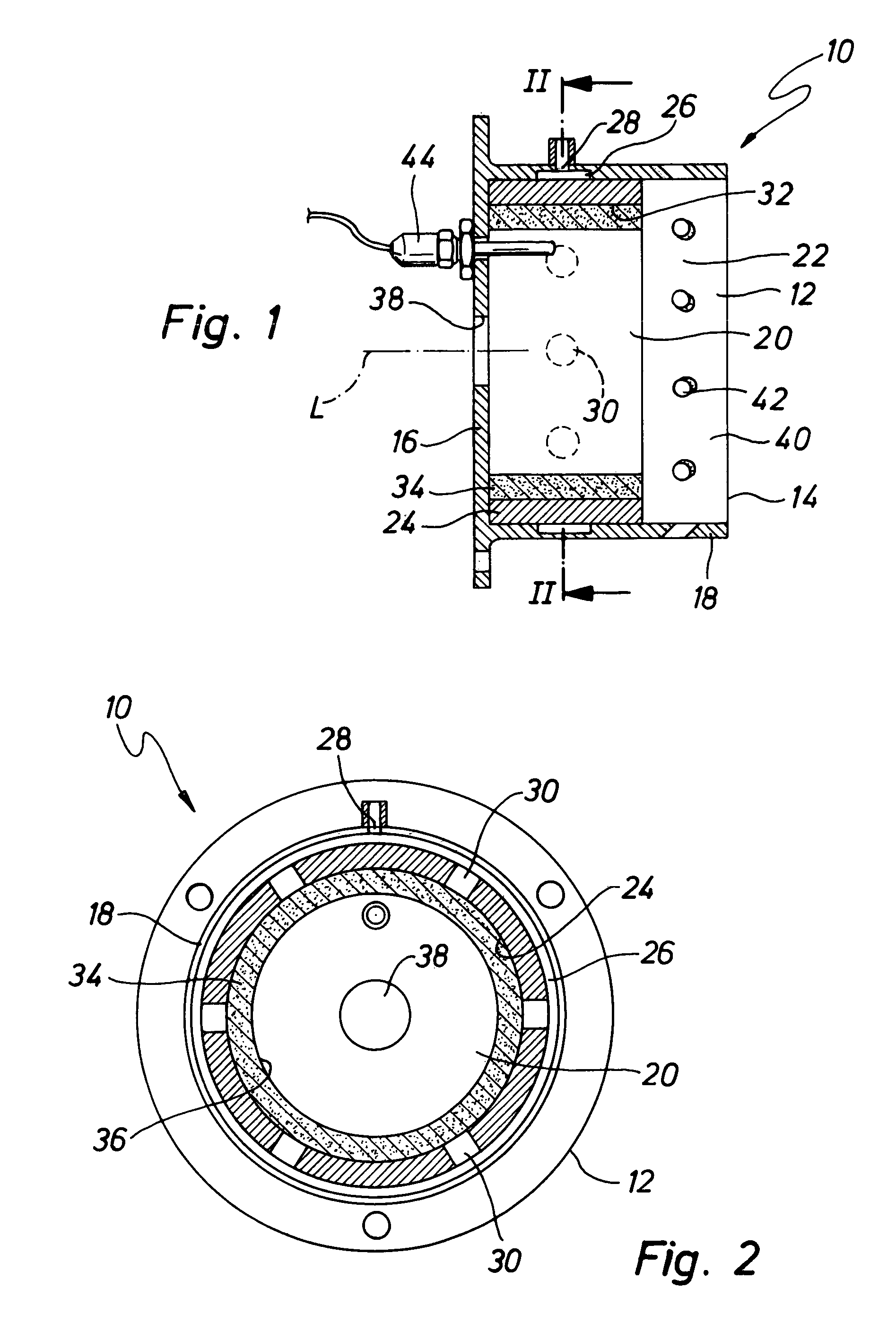
[0017]In the Figures, a combustion chamber subassembly according to the invention is denoted with the reference numeral 10. The combustion chamber subassembly 10 comprises a housing 12, which in general forms a wall 14 with a pot-like structure. This wall 14 includes a floor 16 and adjoining this a substantially cylindrical or else annular peripheral wall 18. A likewise cylindrical or annular fuel distribution element 24 is arranged on an inner side 22 of the peripheral wall surrounding the combustion chamber 20, abuts flush on the inner side 22 of the peripheral wall 18, and in the example shown is positioned adjoining the floor 16. An annular recess 26 is provided, for example by milling out, on the inner side 22 of the peripheral wall 18, and forms a fuel distribution channel 18. Fuel can be introduced into this annular recess 26 through a fuel feed aperture 28 in the peripheral wall 18 via a fuel feed duct (not shown). This recess 26 is closed radially inward with respect to a l...


PUM


Abstract

A combustion chamber subassembly for a vehicle heating device, includes a housing with a housing wall and a fuel feed through the housing wall, a fuel distribution element covering the housing wall on the side facing toward a combustion chamber and together with the housing wall bounding a fuel distribution channel arrangement, a plurality of fuel inlet apertures being formed in the fuel distribution element for conducting fuel from the fuel distribution channel arrangement toward the combustion chamber.

Description

CROSS-REFERENCE TO RELATED APPLICATIONS[0001]Not applicable.STATEMENT REGARDING FEDERALLY SPONSORED RESEARCH OR DEVELOPMENT[0002]Not applicable.BACKGROUND OF THE INVENTION [0003]The present invention relates to a combustion chamber subassembly for a heating device, particularly a vehicle heating device, including a housing with a housing wall and a fuel supply through the housing wall.PRIOR ART [0004]In fuel-operated vehicle heating devices, which are to be built in as auxiliary heating or as supplementary heaters in vehicles or trailers, the mounting position generally depends on the specific vehicle type. The heating performance should however remain constant, independent of the mounting position. In evaporative burners, in which the fuel is delivered into a combustion chamber via a porous medium, the problem exists that the introduction of the fuel into this porous evaporator medium can be impaired by changing the mounting position, since the fuel is generally distributed by grav...

Claims


Application Information

Patent Timeline
Patent Type & Authority Patents(United States)
IPC IPC(8): F23Q3/00F23D14/12F23D3/24F23D3/40
CPCF23D3/40
Inventor WAHL, HERMANNSCHOLZ, PETER
Owner J EBERSPAECHER GMBH & CO KG
Why Eureka
Try Eureka