
Arrangement for an articulated arm robot and method for determining the positioning of a mount for an end effector of an articulated arm robot

an end effector and robot technology, applied in the direction of arms, manipulators, programmed manipulators, etc., can solve the problems of preventing the further operation of the articulated arm robot, the inability to take into account the deformation of the arm links and joints, and the construction in a very stiff manner

Active Publication Date: 2020-05-07
GRADENER ALINA +1
View PDF0 Cites 5 Cited by
  • Summary
  • Abstract
  • Description
  • Claims
  • Application Information

AI Technical Summary

Benefits of technology

This patent text describes a way to improve the positioning of the mount for the end effector of an articulated arm robot. This is accomplished through a parallel arrangement of the arm and a measurement arm that is forced to move in the same way. The position and orientation of the end of the measurement arm can be determined through the signals received from rotary encoders in the joints. This information can then be used to determine the position and orientation of the end of the arm with the mount. This allows for precise positioning of the end effector. The design of the joints is simplified since there is no need for rotary encoders, leading to reduced weight and complexity.

Problems solved by technology

However, in comparison to parallel kinematics they have to be constructed in a very stiff manner.
This means that deformation in the arm links and joints cannot be taken into consideration by the control of the actuators.
In case of an inadmissible deviation of the compared measured values of the multi-axis load sensor and measurement arm a warning signal or emergency signal may be issued, which may ultimately lead to blocking further operation of the articulated arm robot.

Method used


Image

  • Arrangement for an articulated arm robot and method for determining the positioning of a mount for an end effector of an articulated arm robot

Examples


Embodiment Construction

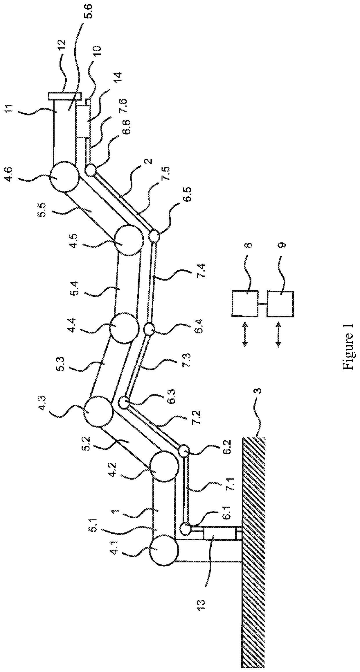
[0026]FIG. 1 shows a schematic view of an arrangement for an articulated arm robot having an articulated arm 1 and a measurement arm 2 configured in parallel thereto. The articulated arm 1 and the measurement arm 2 form a parallel kinematics (parallel arm structures) in such a way that the measurement arm 2 is forced to follow the arm movement performed by the articulated arm 1.

[0027]The articulated arm is mounted on a platform 3 and comprises joints 4.1, 4.2, 4.3, 4.4, 4.5 and 4.6, which are serially connected to each other via the link elements 5.1, 5.2, 5.3, 5.4, 5.5, and 5.6. The FIGURE shows a simplified view. In deviation therefrom one or more of the link elements 5.1, 5.2, 5.3, 5.4, 5.5, and 5.6 may be pointing into the drawing plane at different angles, such as this is known for articulated arm robots.

[0028]The measurement arm 2 comprises measurement joints 6.1, 6.2, 6.3, 6.4, 6.5, and 6.6 as well as measurement arm link elements 7.1, 7.2, 7.3, 7.4, 7.5, and 7.6 connecting t...


PUM


Abstract

An arrangement for an articulated arm robot having an articulated arm and having a measurement arm formed in a parallel kinematic system is provided. The articulated arm includes: joints, each of which has a joint axis; actuators, each actuator being associated with one of the joints; link elements, which connect the joints in a serial articulated arm arrangement; and a mount for an end effector, which mount is arranged at an end of the articulated arm and is configured to hold an end effector. The measurement arm includes: measurement arm joints, each of which has a measurement arm joint axis, which extends coaxially to the joint axis of an associated joint of the articulated arm; rotary encoders, each encoder being associated with one of the measurement arm joints; and measurement arm link elements, which connect the measurement arm joints in a serial measurement arm arrangement.

Description

CROSS-REFERENCE TO RELATED APPLICATIONS[0001]This application claims priority to PCT Application No. PCT / DE2018 / 100635, having a filing date of Jul. 11, 2018, based on German Application No. 10 2017 115 800.6, having a filing date of Jul. 13, 2017, the entire contents both of which are hereby incorporated by reference.FIELD OF TECHNOLOGY[0002]The following relates to an articulated arm robot and a method for determining the positioning of a mount for an end effector of an articulated arm robot.BACKGROUND[0003]Articulated arm robots, which are referred to also as joint arm robots, are three-dimensionally movable industrial robots, the kinematics of which is constructed from several arm links connected to each other in an articulated manner in order to guide an end effector such as grippers or tools. Articulated arm robots permit high mobility. Vertical articulated arm robots are based on a serial kinematics, in which each arm link (link element) is connected to only one further arm l...

Claims


Application Information

Patent Timeline
Patent Type & Authority Applications(United States)
IPC IPC(8): B25J13/08B25J9/16B25J18/00B25J9/06
CPCB25J9/1641B25J13/088B25J18/002B25J9/06B25J18/00
Inventor GRÄDENER, ALINAROKEACH, LEO
Owner GRADENER ALINA
Learn More