Z-axis redundant display/multilayer display

a display component and multi-layer technology, applied in the field of flat panel displays, can solve the problems of little research on the possibility of achieving redundancy using z-axis disposition of redundant display components, and achieve the effects of easy reading, free up surface area, and easy translation of space savings

Inactive Publication Date: 2005-04-07
RAMBUS INC
View PDF7 Cites 83 Cited by
  • Summary
  • Abstract
  • Description
  • Claims
  • Application Information

AI Technical Summary

Benefits of technology

[0004] A first advantage of the present invention where the Z-axis is exploited is that redundancy achieved by exploiting the Z-axis would directly free up surface area on the display console. A second advantage is that the space savings could readily be translated into larger, easier-to-read displays. A third advantage is that system wiring paths would be shorter and thus more reliable. A fourth advantage is an ergonomic one that is particularly apparent in avionics. Since the backup display occupies the exact same location in the console, the user does not have to divert his gaze to another location on the console to acquire important information. All information is displayed in the same place under all conditions.
[0005] If a flat panel display were transparent, there would be little in principle to bar its being stacked in the Z-axis in pairs, or sets of three, etc. Flat panel displays conducive to such configuration must exhibit four properties: they must be inherently transparent, they must fail in the “off mode” to avoid undesirable overlay, they must be relatively thin along the Z-axis, and they must fulfill the survivability criteria for the particular environment calling for redundant implementation. (E.g., an environment requiring redundancy is likely to undergo extremes of temperature, militating against liquid crystal display deployment at the outset. Some severe deployments may require surviving an electromagnetic pulse.)
[0006] Among current display technologies, virtually none exhibit the required transparency. Accordingly, little has been done to explore the possibility of achieving redundancy using Z-axis disposition of the redundant display components. The problem has remained unsolved, although it is surely as urgent as it ever has been.
[0007] The present invention, called Z-Axis Redundant Display / Multilayer Display, achieves this elusive goal for displays that satisfy these four criteria. Among the display technologies that do indeed satisfy these criteria, therefore lending themselves to implementation of a Z-Axis Redundant Display / Multilayer Display, is the display disclosed in U.S. Pat. No. 5,319,491, which is hereby incorporated herein by reference in its entirety.
[0008] The display of U.S. Pat. No. 5,319,491 (hereinafter called a “TMOS Display”) is a known suitable candidate for systemic configuration into a Z-Axis Redundant Display. It exhibits the requisite transparency, it fails in the off-mode without power, and it satisfies the performance / environmental / survivability criteria associated with applications demanding fault tolerance through device redundancy.
[0009] The present invention treats the TMOS Display as a modular element in a larger architectural construct. This construct, broadly conceived, involves the disposition of two or more TMOS Displays in spaced-apart relation to each other, said relation keeping the planes of all constituent TMOS Displays parallel. When TMOS Displays are used as the target module being replicated (as recommended), the interstitial spacing between them is nominally greater than the wavelength of the lowest frequency light traveling in each TMOS Display waveguide to avoid crosstalk between displays occasioned by evanescent coupling. The interstitial gap cannot be filled with material bearing a high refractive index, since TMOS Displays use the principle of Frustrated Total Internal Reflection to generate images. The gap may be filled with air or material with a refractive index very near that exhibited by air (1.00-1.06). The present invention can incorporate displays other than TMOS Displays that fulfill the criteria enunciated above; the limitations inherent in these alternate candidates would directly influence the geometry of the construct. From this point forward, the term “module” will be taken to mean a TMOS Display or a generally equivalent alternate candidate that satisfies the key viability criteria herein tabulated. The term “construct” will refer to the systemic composition of two or more modules in spaced-apart relation to secure the benefits accruing to such composition.

Problems solved by technology

Accordingly, little has been done to explore the possibility of achieving redundancy using Z-axis disposition of the redundant display components.

Method used


Image

  • Z-axis redundant display/multilayer display
  • Z-axis redundant display/multilayer display
  • Z-axis redundant display/multilayer display

Examples


Embodiment Construction

[0034] In the following description, numerous specific details are set forth to provide a thorough understanding of the present invention. However, it will be apparent to those skilled in the art that the present invention may be practiced without such specific details. In other instances, well-known circuits and algorithms have been shown in block diagram form in order not to obscure the present invention in unnecessary detail. For the most part, details involving timing considerations and the like have been omitted inasmuch as such details are not necessary to obtain a complete understanding of the present invention and are within the skills of persons of ordinary skill in the relevant art.

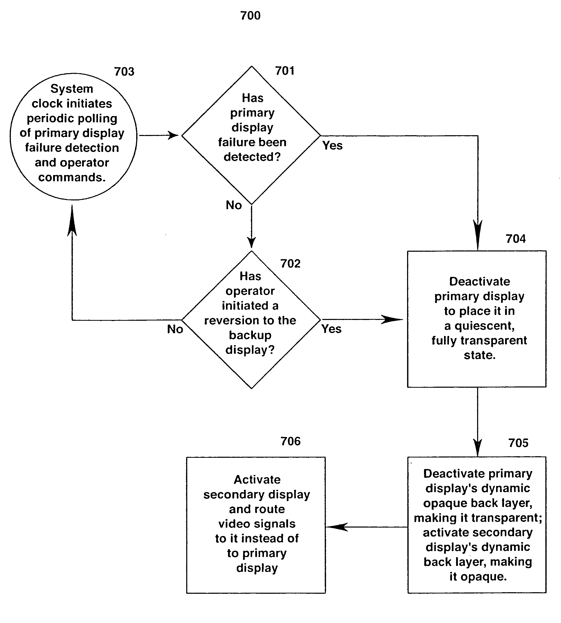
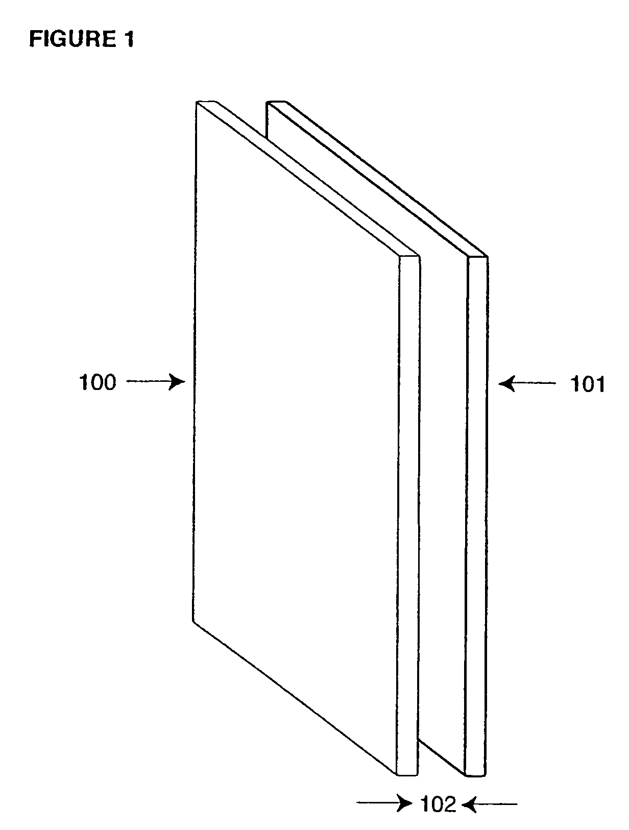
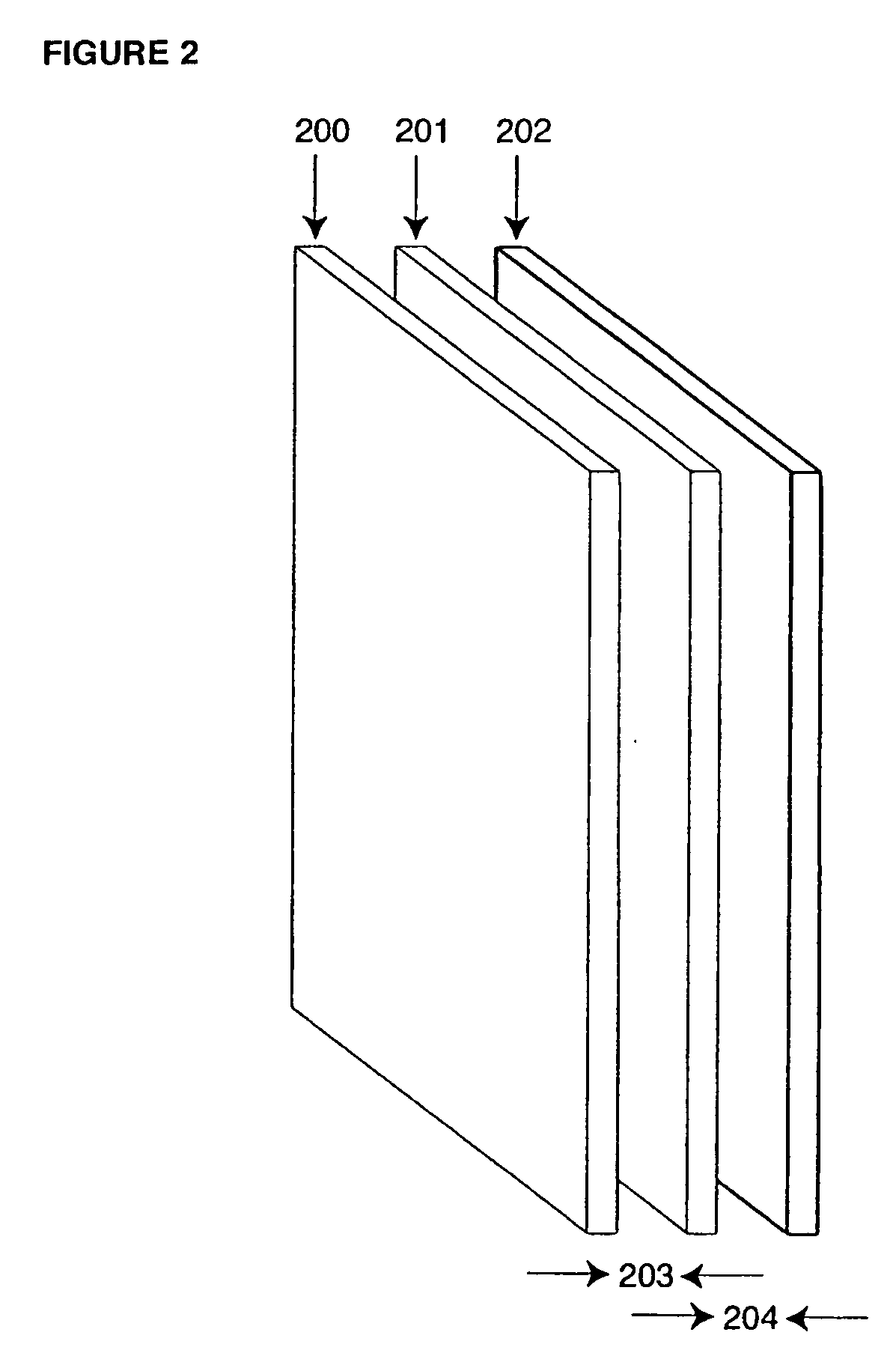
[0035] As stated in the Background Information section, a complement of transparent displays disposed in a spaced-apart relation along the Z-axis (display stacking) can provide valuable system redundancy characteristics in conjunction with improved human factors engineering (identical position ...


PUM


Abstract

A display system for presenting one or more planes of display information. The display system may include two or more display modules positioned in a spaced relationship in a stacked formation substantially along a Z-axis perpendicular to a display face of a display module. Each display module may be selectively activated to display a visual image or deactivated to a quiescent state. Further, when a display module is activated to display the viewed image, the viewed image can be viewed through a prior display module which is deactivated to a quiescent state.

Description

TECHNICAL FIELD [0001] The present invention primarily relates to the field of flat panel displays, particularly as implemented in systems where redundancy is desired and / or required to insure continued display performance in the face of potential device failure. The present invention also applies to multi-level security applications directly exploiting a display exhibiting different classification levels of information displayed on each screen (i.e., hardware separation of different security levels). The present invention also applies to three-dimensional (3D) imaging applications where explicit Z-axis information is viewed directly via overlay replication without recourse to stereoscopic techniques, and even to applications requiring “reality overlay” capability. BACKGROUND INFORMATION [0002] In various critical applications (mission-critical, flight-critical, space-critical) where a display system must exhibit a minimal level of fault tolerance, flat panel displays and their CRT-...

Claims


Application Information

Patent Timeline
Patent Type & Authority Applications(United States)
IPC IPC(8): G06FG09F9/30G09G3/00G09G5/00H04N13/395
CPCB60K2350/2056G02F1/1347G02F2203/62H04N13/0495G09G3/00G09G2300/023G09G2330/08G09F9/30H04N13/395B60K2370/347G09F9/35G09G3/36
Inventor SELBREDE, MARTIN
Owner RAMBUS INC
Why Eureka
Try Eureka