Surface light source and liquid crystal display device using the same

a technology of liquid crystal display device and surface light source, which is applied in the direction of identification means, instruments, lighting and heating apparatus, etc., can solve the problems of difficult device manufacturing, etc., and achieve the effect of simple arrangement, high resolution and easy manufacturing

Active Publication Date: 2005-04-07
ORTUS TECH
View PDF7 Cites 45 Cited by
  • Summary
  • Abstract
  • Description
  • Claims
  • Application Information

AI Technical Summary

Benefits of technology

[0013] Preferably, the surface light source according to this aspect further may comprise a reflecting plate which is placed on an entrance surface side of the prism sheet to face thereto through a space through which illumination light from the light source passes, and reflects the illumination light from the light source. With this reflecting plate, more light from the light source can be made to strike the prism sheet, and hence brighter display can be realized.
[0037] Preferably, in the above liquid crystal display device, the surface light source comprises first and second light source units which selectively emit light of three colors including red, green, and blue, and the control means sequentially selects unit color image data of three colors including red, green, and blue for displaying a left-eye image and unit color image data of three colors including red, green, and blue for displaying a right-eye image in an arbitrary order to sequentially write the data on the respective pixels of the liquid crystal display element during one frame for displaying one 3D image, causes one of the first and second light source units of the surface light source which is located on a right side when viewed from an observation side of the liquid crystal display element to emit light of the three colors including red, green, and blue in synchronism with writing of the unit color image data of the three colors including red, green, and blue for displaying the left-eye image, and causes the light source unit on a left side to emit light of the three colors including red, green, and blue in synchronism with writing of the unit color image data of the three colors including red, green, and blue for displaying the right-eye image. This makes it possible to display 3D color images with high resolution by field sequential display.

Problems solved by technology

This makes it difficult to manufacture the device.

Method used


Image

  • Surface light source and liquid crystal display device using the same
  • Surface light source and liquid crystal display device using the same
  • Surface light source and liquid crystal display device using the same

Examples


first embodiment

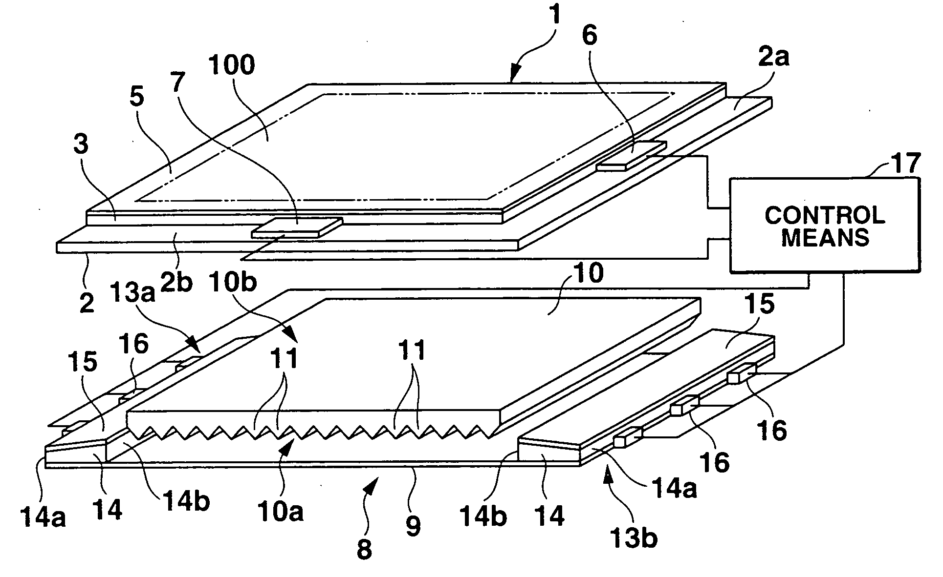
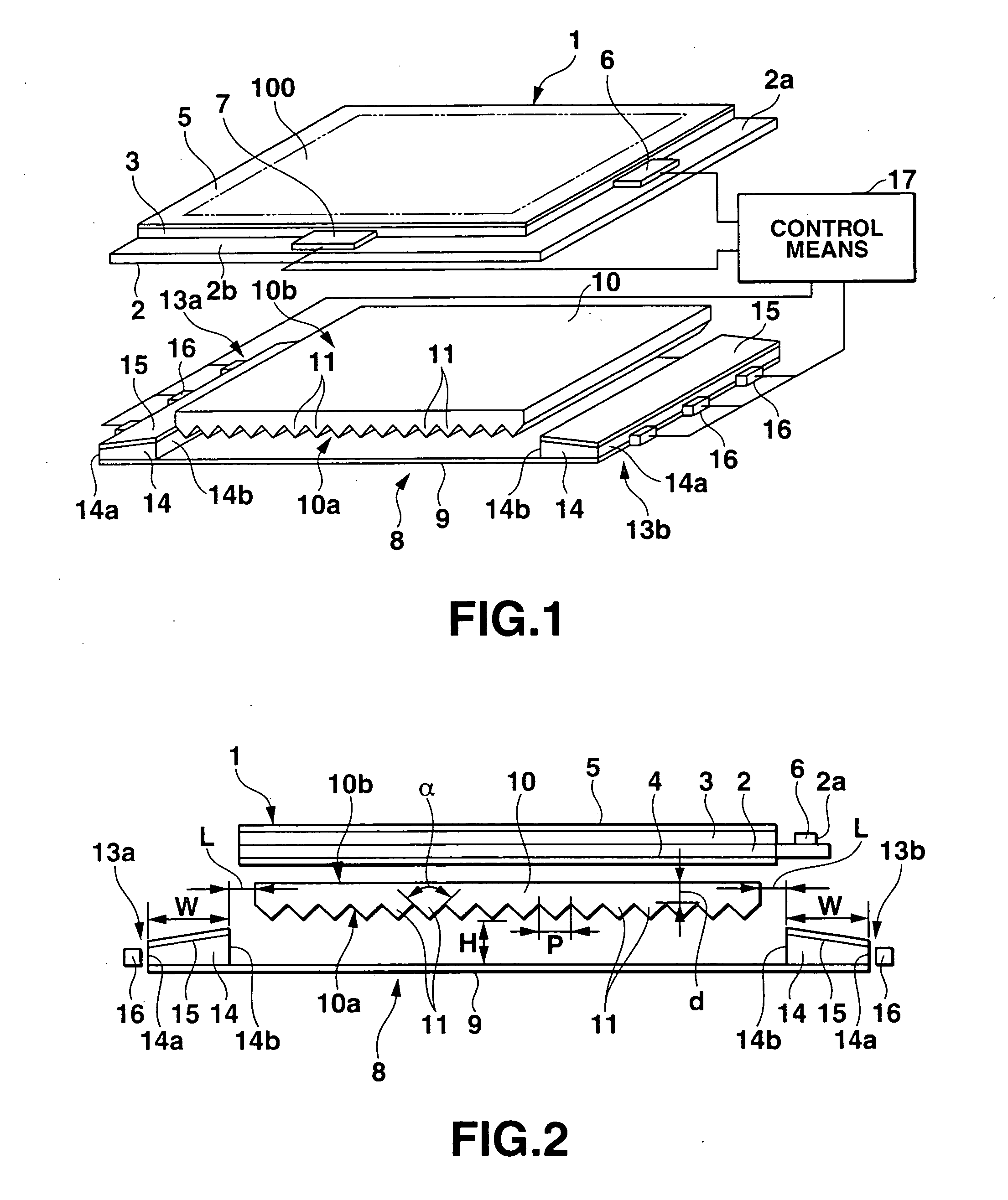
[0046] FIGS. 1 to 5 show the present invention. FIG. 1 is an exploded perspective view of a liquid crystal display device. FIG. 2 is a side view of the liquid crystal display device.

[0047] As shown in FIGS. 1 and 2, this liquid crystal display device includes a liquid crystal display panel 1 which has a display area 100 in which a plurality of pixels (not shown) are arranged in a form of a matrix, with left- and right-eye image data to be respectively observed by the left and right eyes being selectively written on the plurality of pixels, and selectively displays left- and right-eye images in accordance with the left- and right-eye image data. A surface light source 8 is placed on the opposite side to the observation side of the liquid crystal display panel 1 (the upper side in FIG. 1). A control means 17 drives the liquid crystal display panel 1 and surface light source 8.

[0048] The liquid crystal display panel 1 is an active matrix liquid crystal display panel using TFTs (Thin-F...

second embodiment

[0099]FIG. 6 is a side view of a surface light source according to the present invention. A surface light source 8 of this embodiment is obtained by forming a plurality of elongated convex lens portions 12 on an exit surface 10b of a prism sheet 10 so as to be parallel to a plurality of elongated prism portions 11 on an entrance surface 10a of the prism sheet 10, with a vertical angle α of the plurality of elongated prism portions 11 being set within the range of 60° to 80°. Pitches P1 and P2 of the plurality of elongated prism portions 11 and the plurality of elongated convex lens portions 12 are set to 30 μm to 150 μm, and preferably 30 μm to 40 μm.

[0100] The surface light source 8 of this embodiment is designed such that the plurality of elongated convex lens portions 12 are formed on the exit surface 10b of the prism sheet 10, and the vertical angle α of the plurality of elongated prism portions 11 on the entrance surface 10a of the prism sheet 10 and the pitches P1 and P2 of th...


PUM

PropertyMeasurementUnit
vertical angleaaaaaaaaaa
twist angleaaaaaaaaaa
thicknessaaaaaaaaaa

Abstract

A surface light source includes a prism sheet placed on one side of a liquid crystal display panel, and having elongated prism portions formed to form a patterned indented entrance surface having an angular cross-section, and an exit surface. A reflecting plate is placed to face the prism sheet through a space. First and second light source units are disposed on two end sides. A control unit sequentially writes left-eye image data and right-eye image data on respective pixels of the display panel, causes the light source unit on the right side when viewed from an observation side of the surface light source to emit light in synchronism with the writing of the left-eye image data, and causes the light source unit on the left side to emit light in synchronism with the writing of the right-eye image data.

Description

CROSS-REFERENCE TO RELATED APPLICATIONS [0001] This application is based upon and claims the benefit of priority from prior Japanese Patent Application No. 2003-347200, filed Oct. 6, 2003, the entire contents of which are incorporated herein by reference. BACKGROUND OF THE INVENTION [0002] 1. Field of the Invention [0003] The present invention relates to a surface light source having directivity in a predetermined direction, a surface light source for displaying a 3D image on a liquid crystal display panel, and a liquid crystal display device including the surface light source. [0004] 2. Description of the Related Art [0005] The following is known as a conventional liquid crystal display device designed to display a 3D image. In the device, a left-eye image is displayed by pixels on alternate lines of a liquid crystal display panel, and a right-eye image is displayed by pixels on the remaining alternate lines. The device then allows a display observer to observe the left- and right-...

Claims


Application Information

Patent Timeline
Patent Type & Authority Applications(United States)
IPC IPC(8): F21S8/02F21V8/00F21Y101/02G02F1/133G02F1/1335G02F1/13357G09F9/00
CPCG02F1/133615G02F1/133504G02F1/1335
Inventor DAIKU, YASUHIROMUTO, TETSUO
Owner ORTUS TECH
Why Eureka
Try Eureka