
Data transmission device, data transmission method, data transmission program, data reception device, data reception method, data reception program, and communication system

a data transmission and data technology, applied in the field of data transmission devices, can solve the problems of deteriorating the efficiency of data transmission, not supporting the function of easily generating and transmitting a reception, etc., and achieve the effect of avoiding the reduction of data transmission efficiency

Active Publication Date: 2005-04-07
SHARP KK
View PDF9 Cites 28 Cited by
  • Summary
  • Abstract
  • Description
  • Claims
  • Application Information

AI Technical Summary

Benefits of technology

[0032] The present invention is done to solve the above-described problems inherent in the conventional arts. The objective of the present invention is, for instance, to provide a data transmission device which can avoid the reduction of data transmission efficiency, by properly carrying out retransmission when a communication error (e.g. a reception error and transmission error)
[0043] In other words, the present transmission device attempts to avoid the occurrence of the communication error due to the data format, by altering the data format of the transmission data and retransmitting the same.
[0045] Further, a communication system including the present transmission device can carry out efficient data transmission.
[0051] With this arrangement, the present reception device can manage the related sets of transmission data, in a systematic manner. For instance, the present reception device can easily determine whether or not the retransmission data concerning the initial transmission data having been failed to process is received (the user can easily make this determination, too).
[0053] Moreover, a communication system including the above-mentioned present reception device and present transmission device can efficiently carry out data transmission.

Problems solved by technology

However, this Internet facsimile system has the following inherent problem which is not observed in a typical facsimile communication.
However, the conventional arrangement does not support such a function of easily generating and transmitting a reception result mail.
However, in this conventional Internet facsimile machine, when a transmission error or reception error (errors indicating that an e-mail message cannot be properly processed due to the receiving-end machine) occurs for any reason, the e-mail message is not retransmitted in order to prevent the continuous occurrence of errors.
For this reason, the conventional Internet facsimile machine cannot complete the transmission if an error occurs, and this deteriorates the efficiency of the data transmission.

Method used


Image

  • Data transmission device, data transmission method, data transmission program, data reception device, data reception method, data reception program, and communication system
  • Data transmission device, data transmission method, data transmission program, data reception device, data reception method, data reception program, and communication system
  • Data transmission device, data transmission method, data transmission program, data reception device, data reception method, data reception program, and communication system

Examples


first embodiment

[0093] The following will describe one embodiment of the present invention.

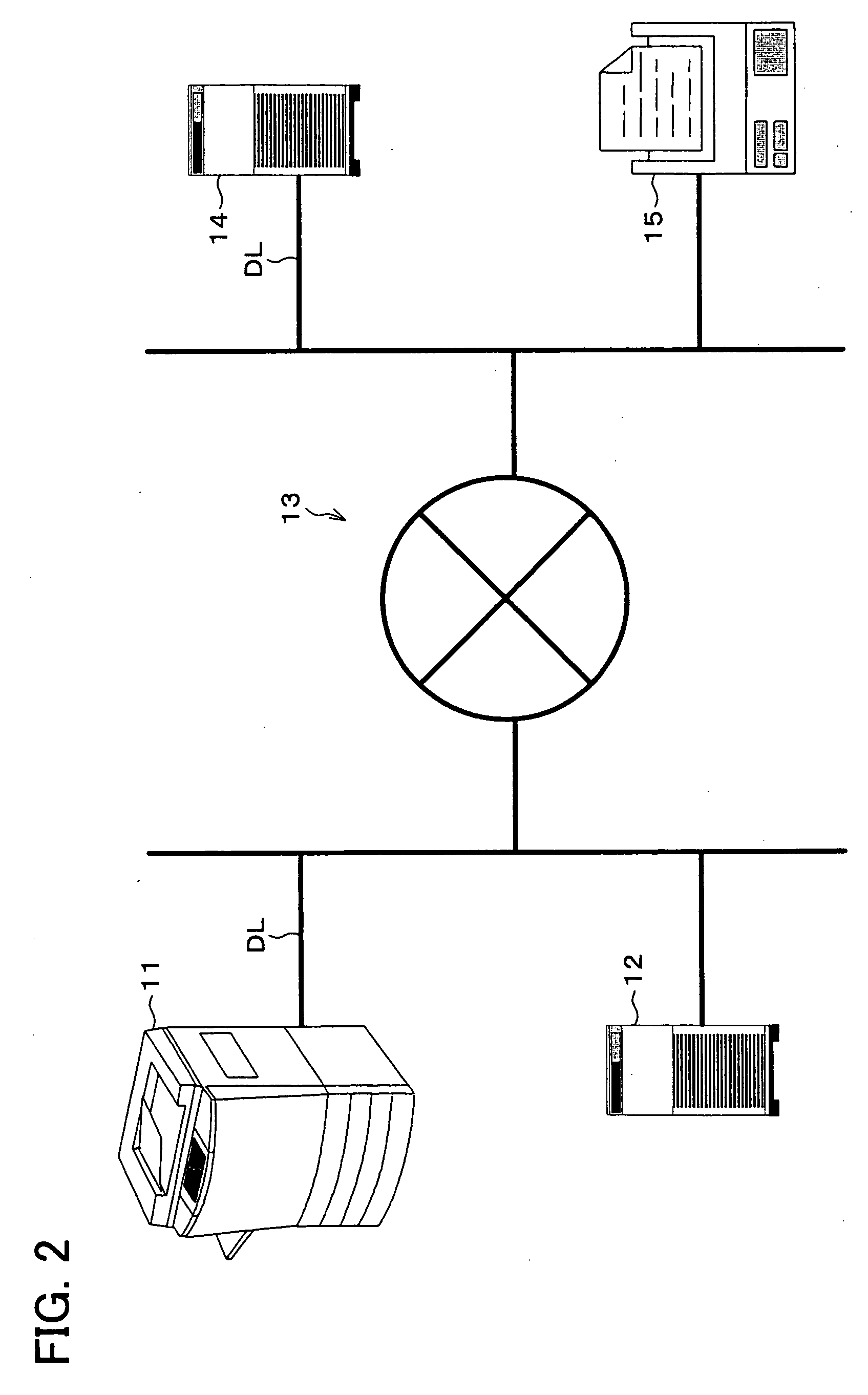
[0094] A communication system according to the present embodiment (present system) is a wide area network system in which multiple LANs (Local Area Network) are connected over the Internet and the public switched telephone network (PSTN), including many devices such as terminal device capable of the Internet Fax communication (Internet facsimile machine) and e-mail server.

[0095] In the present system, each of the Internet facsimile machines has a MDN (Message Disposition Notification) function, so that the Internet Fax communication can be carried out among the Internet facsimile machines through the use of the MDN function.

[0096] Here, the Internet Fax communication (hereinafter referred to as INF communication) is a communication method of transmitting and receiving an e-mail message including image data of the original document captured (scanned). In the INF communication, printing image data included i...

second embodiment

[0296] The following will describe Second Embodiment of the present invention. By the way, members having the same functions as those described in First Embodiment are given the same numbers, so that the descriptions are omitted for the sake of convenience.

[0297] First Embodiment have chiefly described the transmission of an image mail in the digital multifunction device 11.

[0298] In the present embodiment, on the other hand, the receiving of an image mail in the digital multifunction device 11 in an efficient manner will be described.

[0299] As shown in First Embodiment, the present system is arranged such that, when an image mail being transmitted is not processable, to inform this, a reception result mail is supplied to a transmitting-end machine. Receiving the reception result mail, the transmitting-end machine alters the image format of the image mail in accordance with the instruction of the reception result mail, and retransmits the altered image mail.

[0300] In this manner...


PUM


Abstract

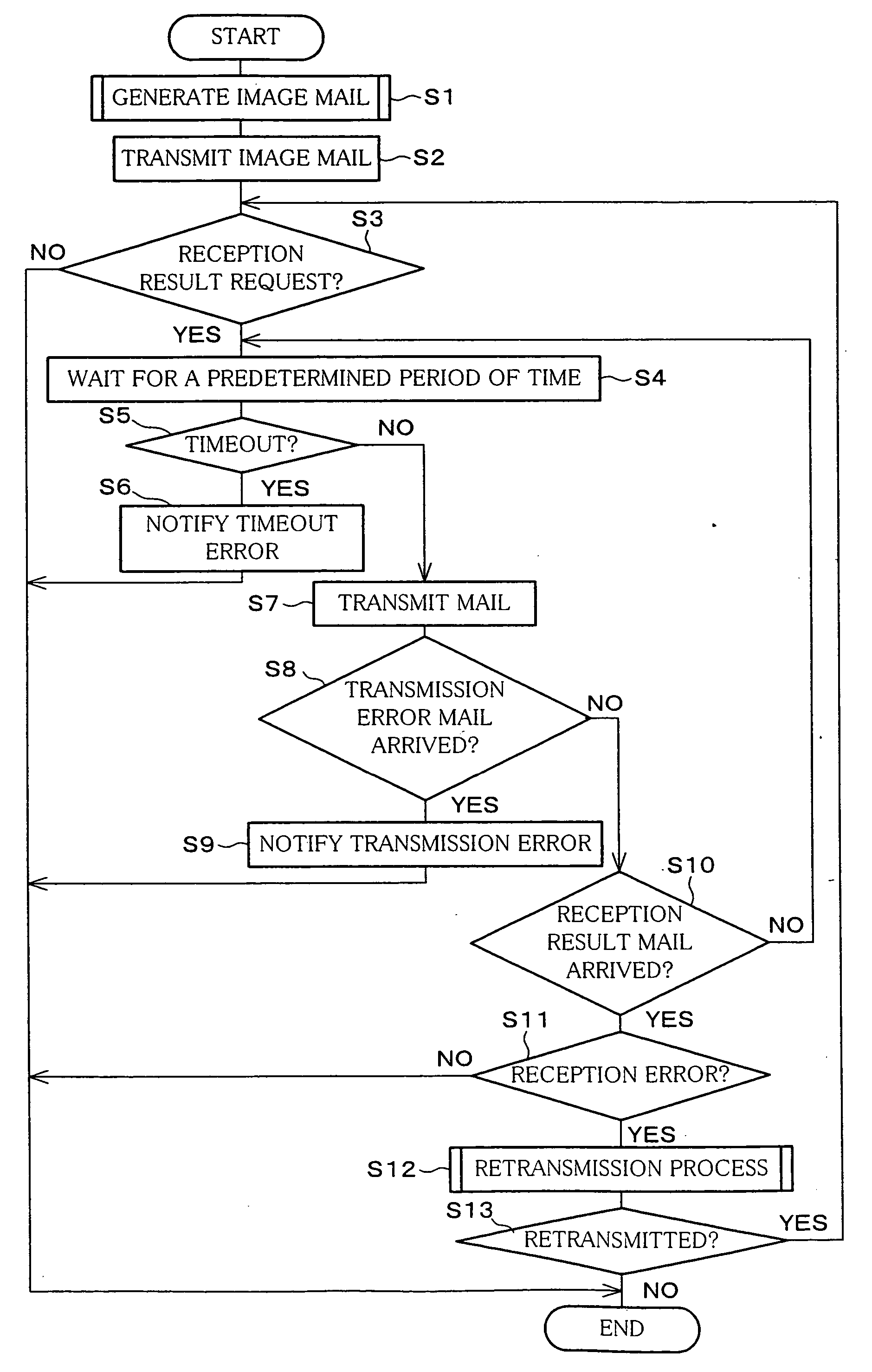
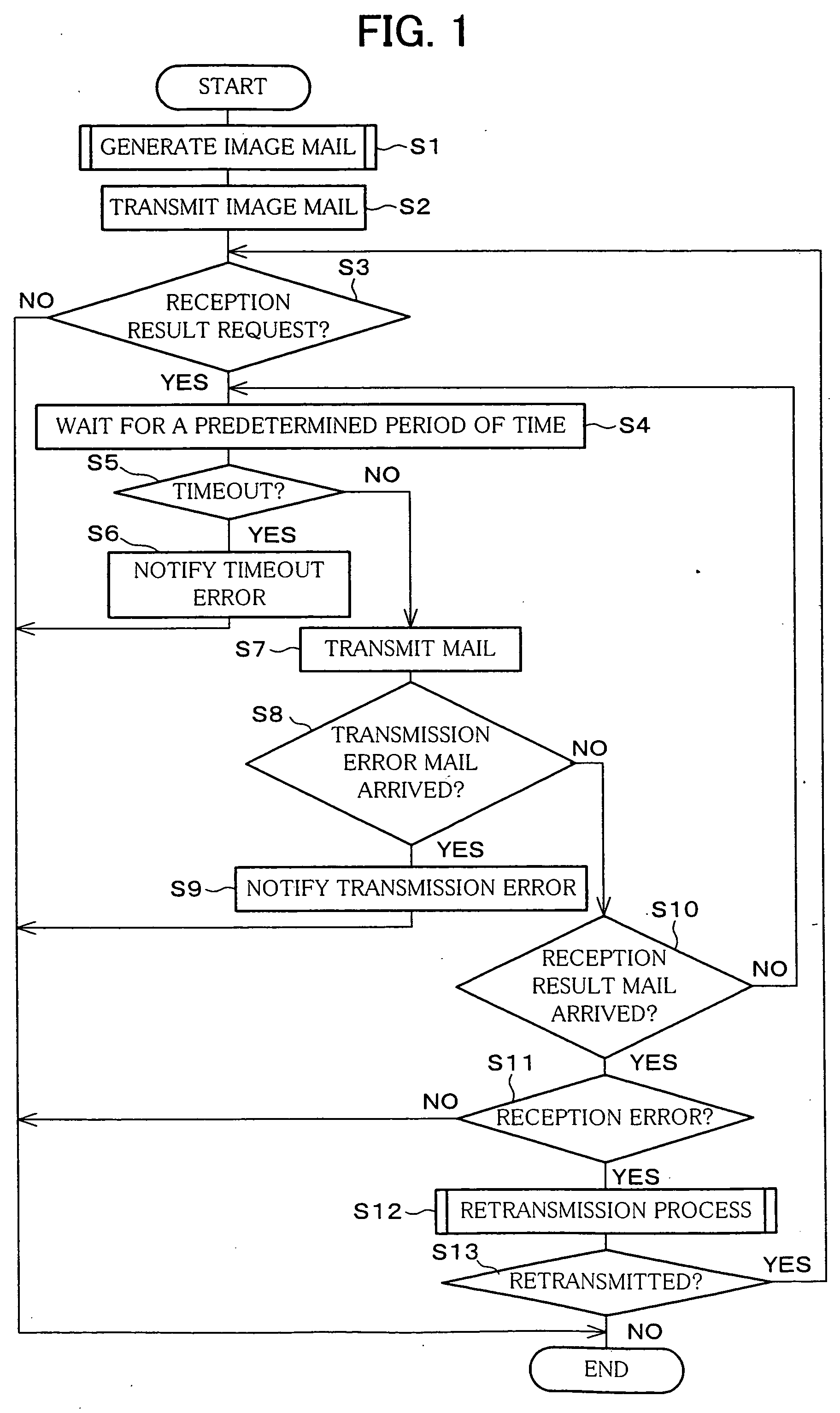
In the present invention, after an image mail is transmitted to a receiving-end machine (S1, S2), when a reception error occurs, an image format of image data in the image mail is altered, and the image mail including this image data (retransmission image mail) is retransmitted to the receiving-end machine (S3 through S13). That is, it is attempted to avoid the occurrence of the communication error due to the image format, by altering the image format of the image data and retransmitting the same. With this arrangement, it is possible to avoid successive occurrence of the communication errors, even if the transmission data is retransmitted. Thus, as compared to the arrangements in which retransmission is not carried out at all or identical transmission data is retransmitted, the present arrangement can improve the efficiency of data transmission.

Description

FIELD OF THE INVENTION [0001] The present invention relates to a data transmission device in which the reception result of transmission data is confirmed on ground of a reception result notification from a receiving-end machine, and a data reception device which receives the transmission data and returns a reception result notification corresponding to the reception result. BACKGROUND OF THE INVENTION [0002] Recent development of networking has created new applications for network communication devices for communication over the Internet or like network. [0003] For instance, there are scanner communication devices which can transmit image information read from a document to an external device (e.g. a computer) connected to a network. [0004] As an example of such scanner communication devices, a device having “Scan to Email” function has been developed. [0005] This device converts the image information read from a document to data with a particular format so as to generate an attachm...

Claims


Application Information

Patent Timeline
IPC IPC(8): G03B27/42G06F13/00H04L1/08H04M11/00H04N1/00H04N1/32
CPCG03B27/42
Inventor TANIGUCHI, TSUTOMUNAKAMURA, TAKESHIMORI, TAMOTSUNAKABAYASHI, MAKOTO
Owner SHARP KK
Learn More