Hybrid electro-active lens

a technology of electro-active lenses and hybrid lenses, applied in the field of lenses, can solve the problems of limited use and limited use of conventional lenses

Inactive Publication Date: 2005-04-07
E VISION LLC
View PDF4 Cites 172 Cited by
  • Summary
  • Abstract
  • Description
  • Claims
  • Application Information

AI Technical Summary

Problems solved by technology

As such, a conventional lens may provide limited use.
However, this bifocal lens has fixed focal length regions, which also provides limited use.

Method used


Image

  • Hybrid electro-active lens
  • Hybrid electro-active lens
  • Hybrid electro-active lens

Examples


Embodiment Construction

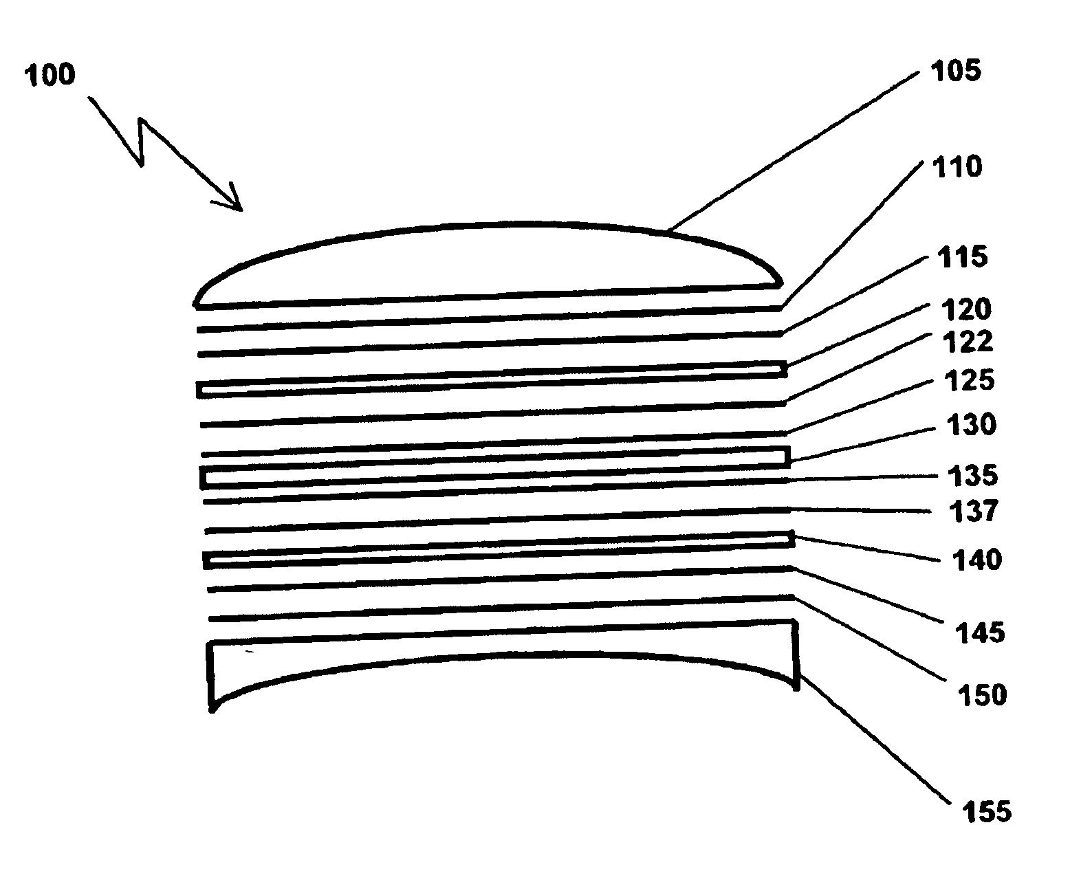
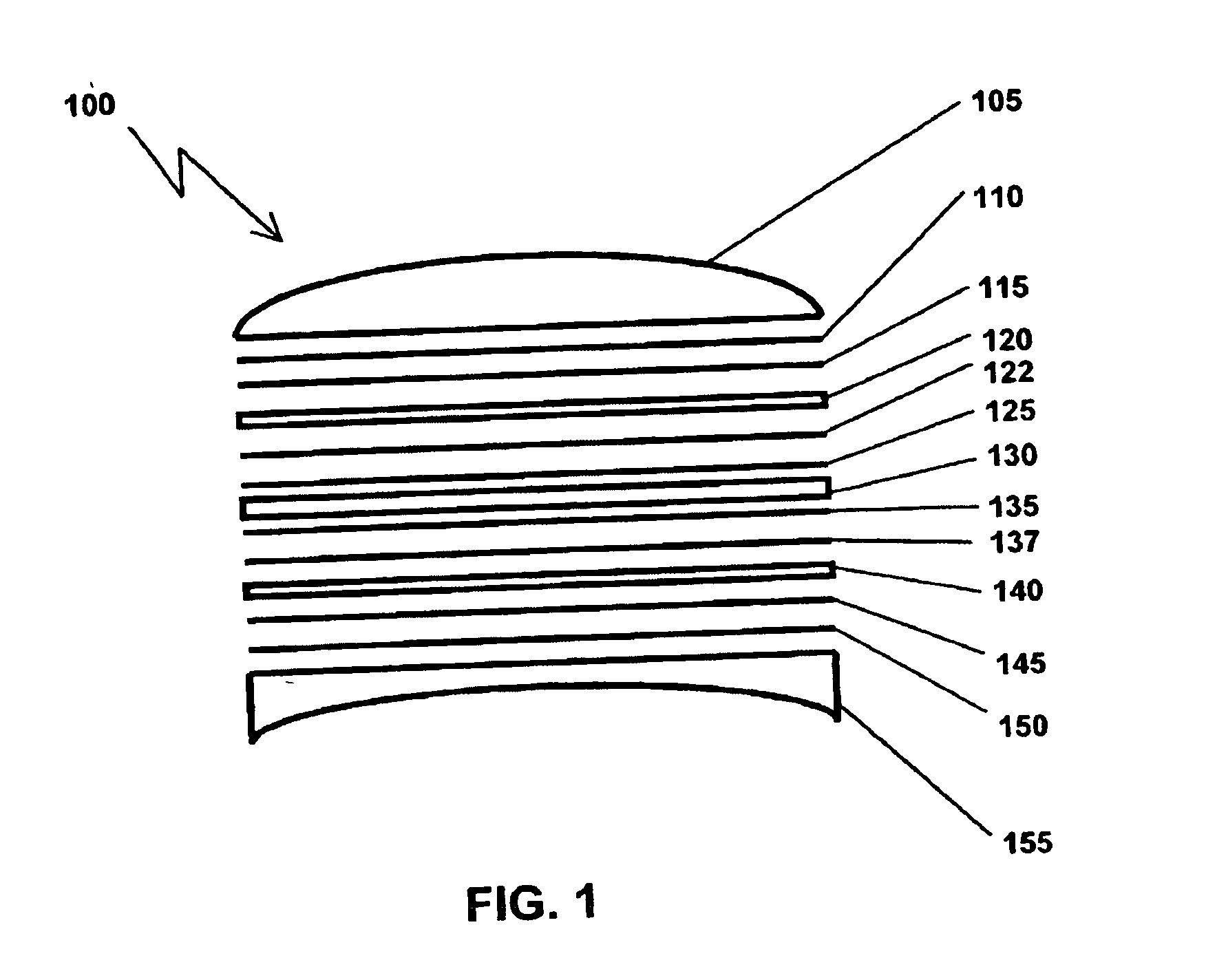
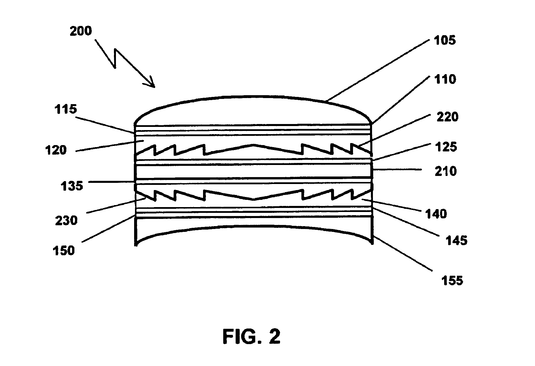
Embodiments of an electro-active lens of the present invention may be a composite lens made up of various components, including optically transmissive material, e.g., liquid crystals, that may have variable refractive indices. The variable focal lengths may be provided, for example, by diffractive patterns etched or stamped on the lens or by electrodes disposed on the optically transmissive material of the lens. The diffractive patterns refract light entering the optically transmissive material, thereby producing different amounts of diffraction and, hence, variable focal lengths. The electrodes apply voltage to the optically transmissive material, which results in orientation shifts of molecules in the material, thereby producing a change in index of refraction, this change in index of refraction can be used to match or mismatch the index of the liquid crystal with the material used to make the diffractive pattern. When the liquid crystal's index matches that of the diffractive pa...


PUM

PropertyMeasurementUnit
voltageaaaaaaaaaa
thicknessaaaaaaaaaa
thicknessaaaaaaaaaa

Abstract

An electro-active lens is disclosed. The lens includes at least one electro-active cell to provide a lens having at least two focal lengths, the electro-active cell capable of adjusting its focal length based on voltages applied to the electro-active cell. The voltage is supplied by an alternating current source, including a flying capacitor circuit. The electro-active lenses reduce birefringence through the use of a single cholesteric liquid crystal electro-active cell.

Description

FIELD OF THE INVENTION The present invention generally regards lenses. More specifically the present invention regards composite electro-active lenses. BACKGROUND OF THE INVENTION Generally, a conventional lens has a single focal length to provide a particular visual acuity. The lens may be produced for a particular lens wearer or application where there is no change in visual acuity or no need to modify the visual acuity for different viewing distances. As such, a conventional lens may provide limited use. A bifocal lens was created to provide multiple focal lengths for the lens wearer or application where there is a need for varying visual acuity, for example, for reading and distance vision. However, this bifocal lens has fixed focal length regions, which also provides limited use. In each of these examples, the lens is ground from a single material.BRIEF DESCRIPTION OF THE DRAWINGS FIG. 1 is an exploded cross-sectional view of an electro-active lens in accord with an embodim...

Claims


Application Information

Patent Timeline
Patent Type & Authority Applications(United States)
IPC IPC(8): G02B17/06G02B17/08G02B27/01G02C7/10G02F1/1333G02F1/1335G02F1/1343G02F1/29
CPCG02B27/017G02C7/048G02C7/083G02C7/101G02F2001/294G02F1/133553G02F1/134309G02F1/29G02F2001/13415G02F1/133371B29D11/00817B29D11/00009G02F1/13415G02F1/294B29D11/0073
Inventor MEREDITH, GERALDKIPPELEN, BERNARDMATHINE, DAVID
Owner E VISION LLC
Why Eureka
Try Eureka