This helps you quickly interpret patents by identifying the three key elements:
Problems solved by technology
Method used
Benefits of technology
Benefits of technology
It is an object of the present invention to provide a video coding method enabling implementation of resolution scalability, while improving the coding efficiency.
It is a subject matter of the present invention performing band division on an original image (first-resolution image) with high resolution to generate a low-frequency component (second-resolution image component) and other sub-band components (horizontal component, vertical component and diagonal component), subjecting each sub-band component to DCT processing and coding processing (for example, bit-plane VLC), and thereby generating a video stream enabling the resolution to be selected after coding with high efficiency.
Problems solved by technology
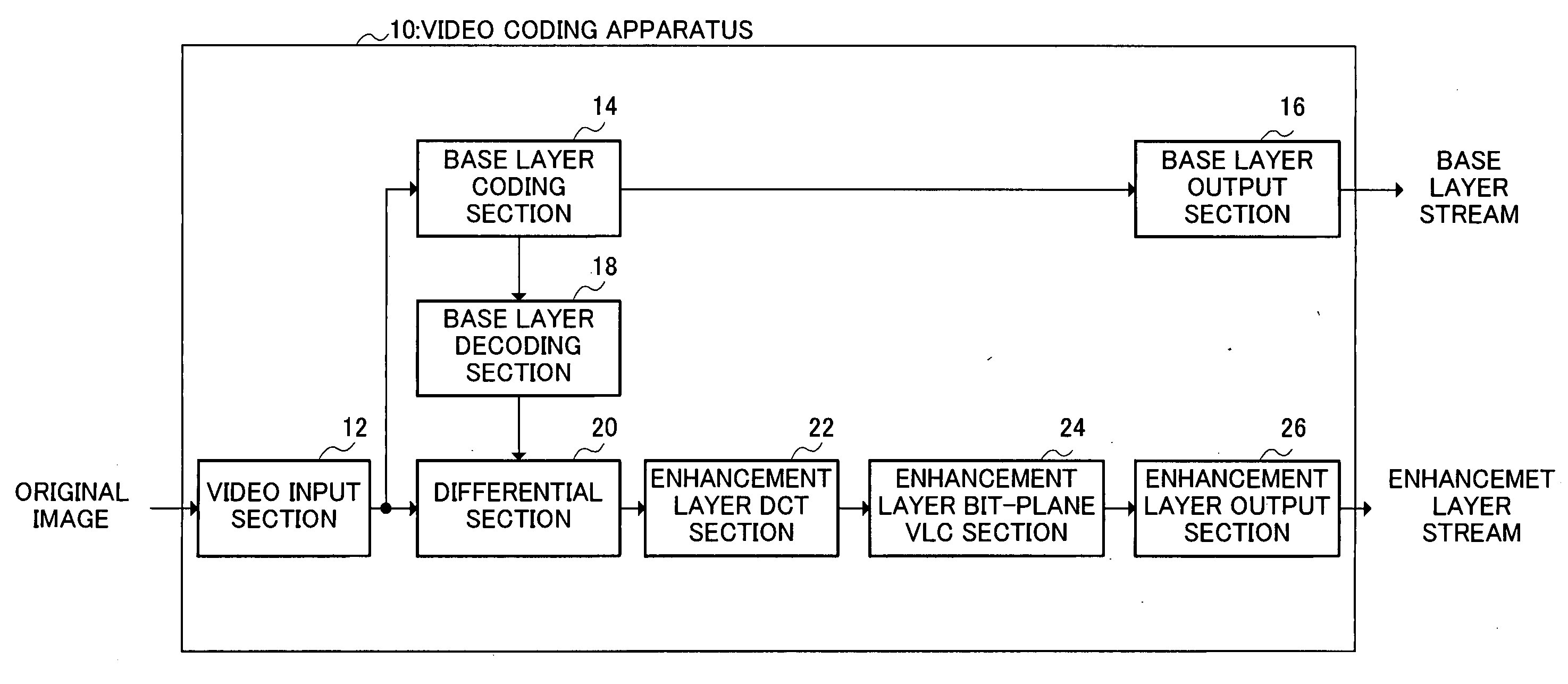
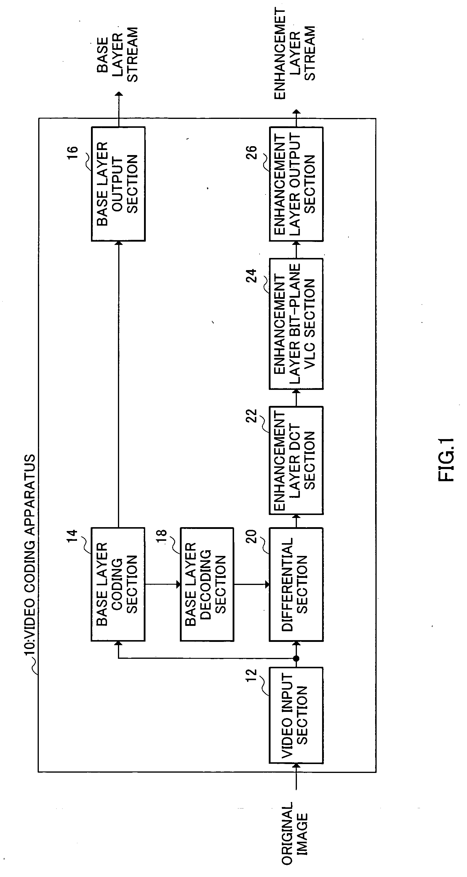
However, in conventionally used video coding techniques such as H.261 standard and MPEG (Moving Picture Experts Group) standard, the amount of code used in decoding is determined uniquely after the data is once coded, and therefore, it is not possible to vary the quality of video to replay.
However, in the video coding apparatus as described in the above-mentioned patent publication, it is possible to perform scalable coding with two-stage resolutions on input video of high resolution, but processing of quantization and VLC is simply used as coding processing of high-region component, and any consideration is not given to coding efficiency.
Method used
Image
Click on the blue label to locate the original text in one second.
Reading with bidirectional positioning of images and text.
Examples
embodiment 1
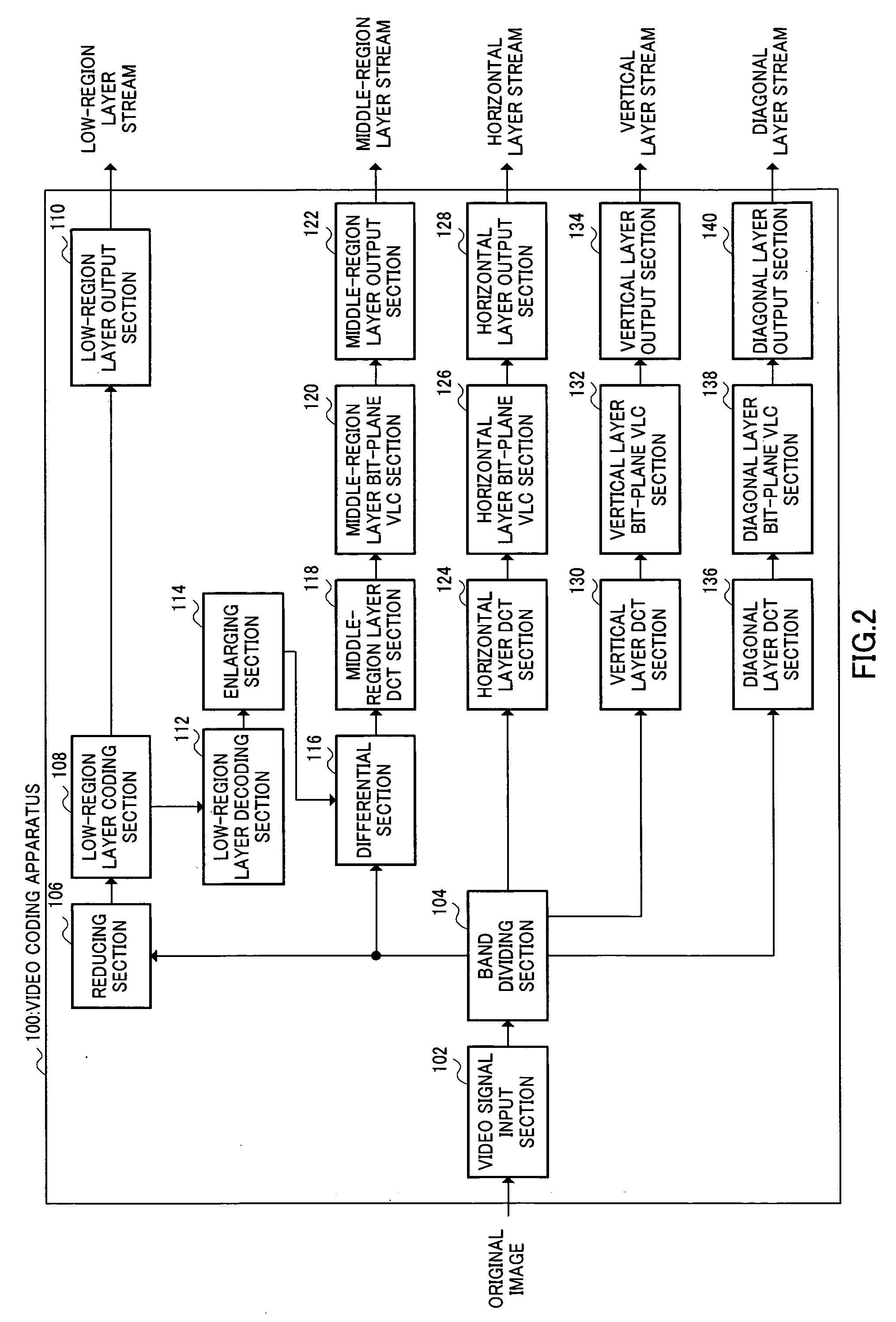
FIG. 2 is a block diagram illustrating a configuration of a video coding apparatus to which is applied a video coding method according to Embodiment 1 of the present invention.
FIG. 22 is a block diagram illustrating a configuration of a video coding apparatus to which is applied a video coding method according to Embodiment 2 of the present invention. In addition, video coding apparatus 300 has a basic configuration similar to that of video coding apparatus 100 as shown in FIG. 2, and the same structural elements are assigned the same reference numerals to omit specific descriptions thereof.
It is a feature of this Embodiment to multiplex a horizontal, vertical and diagonal layer streams onto a signal stream. Therefore, substituting for horizontal layer bit-plane VLC section 126, horizontal layer output section 128, vertical layer bit-plane VLC section 132, vertical layer output section 134, diagonal layer bit-plane VLC section 138 and diagonal layer output secti...
FIG. 29 is a block diagram illustrating a configuration of a video decoding apparatus to which is applied a video decoding method according to Embodiment 3 of the present invention. In addition, video decoding apparatus 500 has a basic configuration similar to that of video decoding apparatus 200 as shown in FIG. 16, and the same structural elements are assigned the same reference numerals to omit specific descriptions thereof.
It is a feature of this Embodiment to receive and decode a stream generated in video coding apparatus 100 of Embodiment 1 corresponding to the display resolution, processing capability and transmission rate. Therefore, substituting for low-region layer input section 202, middle-region layer input section 210, horizontal layer input ...
PUM
Abstract
A video coding method enabling implementation of resolution scalability while improving the coding efficiency. In the method, a band dividing section 104 performs band division on a high-resolution original image to generate a middle-resolution image, horizontal component, vertical component and diagonal component. The horizontal component is subjected to the DCT processing in horizontal layer DCT section 124, and then subjected to the bit-plane VLC processing in horizontal layer bit-plane VLC section 126. The vertical component is subjected to the DCT processing in vertical layer DCT section 130, and then subjected to the bit-plane VLC processing in vertical layer bit-plane VLC section 132. The diagonal component is subjected to the DCT processing in diagonal layer DCT section 136, and then subjected to the bit-plane VLC processing in diagonal layer bit-plane VLC section 138. In scanning, a scanning order is determined in consideration of bias in the distribution of DCT coefficients for each band component.
Description
BACKGROUND OF THE INVENTION 1. Field of the Invention The present invention relates to a video coding method having resolution scalability. 2. Description of Related Art Video has already been closely-linked to our lives and invaluable which causes us to enjoy visual information in various display terminals such as personal computers, mobile phones, televisions and hi-vision televisions through transmission means such as the internet, mobile-phone networks, broadcast waves and storage media. In order to transmit information to users efficiently, video signals are compressed into video streams with a smaller amount of data using video coding techniques. Recently, video stream transmission has become widespread where received video coded data is replayed sequentially, instead of replaying the video coded data after downloading all the data. However, in conventionally used video coding techniques such as H.261 standard and MPEG (Moving Picture Experts Group) standard, the amount o...
Claims
Application Information
Patent Timeline
Application Date:The date an application was filed.
Publication Date:The date a patent or application was officially published.
First Publication Date:The earliest publication date of a patent with the same application number.
Issue Date:Publication date of the patent grant document.
PCT Entry Date:The Entry date of PCT National Phase.
Estimated Expiry Date:The statutory expiry date of a patent right according to the Patent Law, and it is the longest term of protection that the patent right can achieve without the termination of the patent right due to other reasons(Term extension factor has been taken into account ).
Invalid Date:Actual expiry date is based on effective date or publication date of legal transaction data of invalid patent.

