Landfill gas extraction flare

a technology of gas extraction and landfill, which is applied in the direction of incinerator equipment, combustion types, lighting and heating equipment, etc., can solve the problem of not achieving better turndown ratios

Inactive Publication Date: 2005-04-07
LFG & E INT
View PDF8 Cites 33 Cited by
  • Summary
  • Abstract
  • Description
  • Claims
  • Application Information

AI Technical Summary

Problems solved by technology

The reason that better turndown ratios have not been achieved are many, but include the fact that most flares cannot be optimized for any particular methane flow rate, but instead must be able to burn methane at what often are widely varying and unpredictable methane flow rates.

Method used


Image

  • Landfill gas extraction flare
  • Landfill gas extraction flare
  • Landfill gas extraction flare

Examples


Embodiment Construction

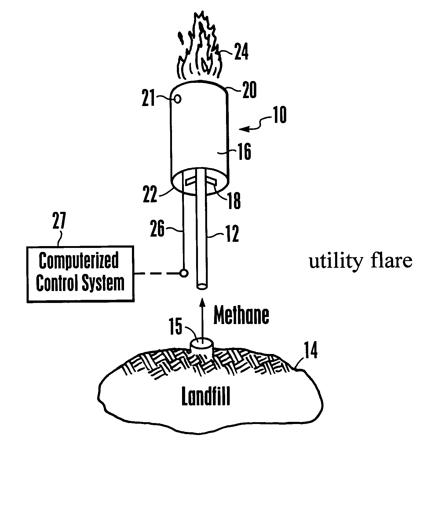
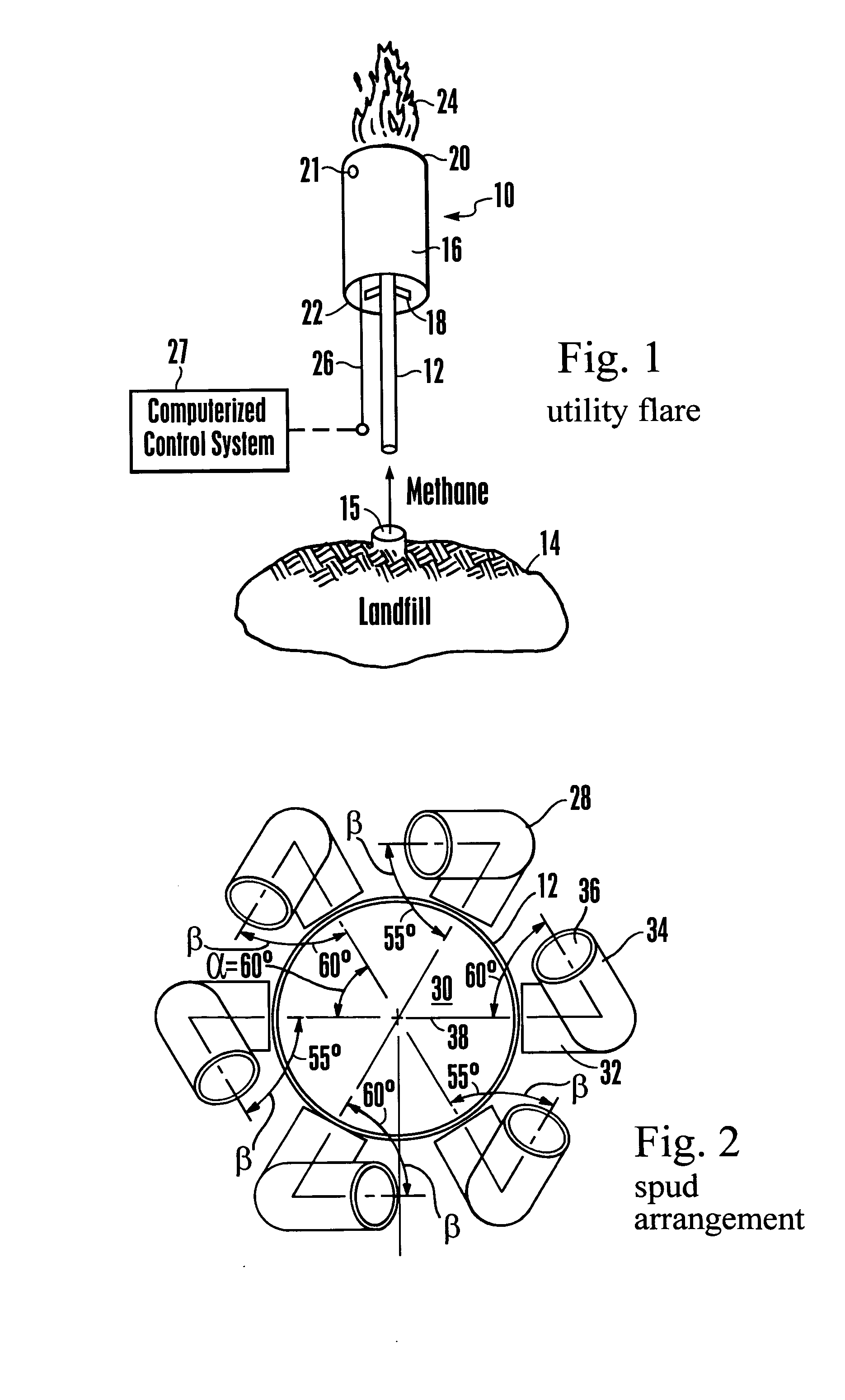
[0020] Referring initially to FIG. 1, a flare is shown, generally designated 10, that includes a methane riser 12 in fluid communication with a landfill 14 for removing methane gas from the landfill 14. A methane pump or blower 15 can be provided to direct methane gas to the methane riser 12.

[0021] The flare 10 includes a shroud 16 surrounding the methane riser 12, if desired in a coaxial relationship and radially spaced therefrom, with the shroud 16 being located above the ground. Brackets 18 can connect the shroud 16 and the methane riser 12. The shroud 16 has an open top end 20. An ignition device 21 can be provided near the open top end 20 to provide an ignition spark within the flare 10. If desired, the shroud 16 can have an open bottom end 22. When burning methane, a flame 24 appears inside and above the open top end 20. Also, a louver actuator 26 is disposed in the shroud 16 and has an end that extends outside the shroud 16 for purposes to be shortly disclosed. It is to be u...


PUM


Abstract

A landfill methane burner flare has a methane riser within a shroud. The methane riser terminates in a series of spuds that are bent to promote turbulence and mixing in methane passing through and out of the spuds. Louvers can be positioned in the riser to selectively establish a methane gas pressure within the riser, and / or louvers can be positioned between the methane riser and shroud to selectively establish combustion air flow in the flare.

Description

I. FIELD OF THE INVENTION [0001] The present invention relates generally to landfill gas extraction systems. II. BACKGROUND OF THE INVENTION [0002] Landfills produce methane gas which must be extracted from the landfills. In some cases, this can be done passively, simply by placing open pipes in the landfill through which the methane can vent. For environmental reasons, however, many localities require that the methane be eliminated as much as possible by actively directing the methane through a flare, which burns the gas. [0003] Two types of flares are generally provided. The first type is referred to as a utility flare, which has a cylindrical shroud with an open top, above which a flame appears when the flare is burning gas. A methane riser extends from the ground into the shroud, with the bottom of the shroud generally being above the ground and supported on the riser. The methane is pumped up through the riser and out of an outlet into the shroud, where an ignition device ignit...

Claims


Application Information

Patent Timeline
Patent Type & Authority Applications(United States)
IPC IPC(8): F23D14/00F23G5/34F23G7/08
CPCF23G7/08F23G5/34
Inventor BROOKSHIRE, RONALD L.BROOKSHIRE, IRAVIS J.
Owner LFG & E INT
Why Eureka
Try Eureka