

Adaptive hill hold for automobile applications by redundant clutch apply
- Summary
- Abstract
- Description
- Claims
- Application Information
AI Technical Summary
Benefits of technology
Problems solved by technology
Method used
Image

Examples
Embodiment Construction
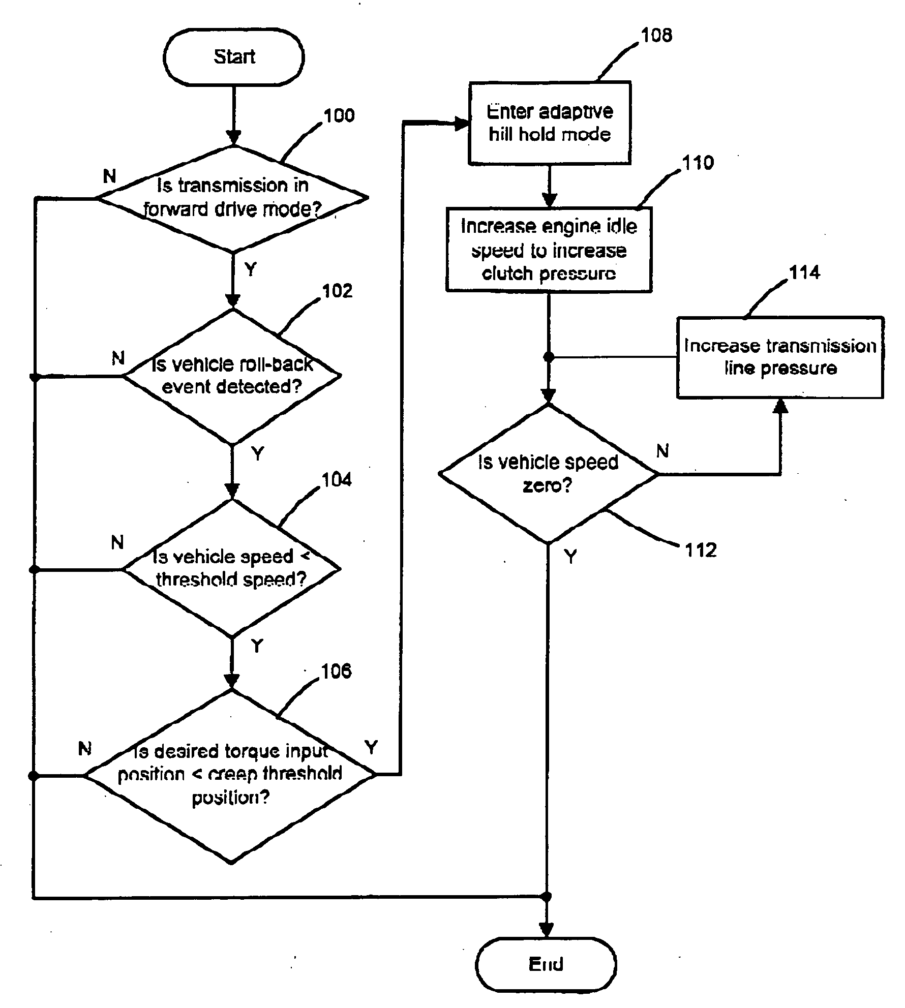
[0015] The following description of the preferred embodiments is merely exemplary in nature and is in no way intended to limit the invention, its application, or uses. For purposes of clarity, the same reference numbers will be used in the drawings to identify similar elements.
[0016] Referring now to FIG. 1, a vehicle 10 is schematically illustrated. The vehicle 10 includes an engine 12 that drives a transmission 14 though a torque converter 16. Air is drawn into the engine 12 through a throttle 18. The air is mixed with fuel and combusted within cylinders (not shown) of the engine 12 to produce drive torque. The transmission 14 is a multi-speed automatic transmission that transfers the engine torque at various gear ratios to drive an output shaft 20. A range selection device 22 enables an operator to set the transmission 14 at a desired operating mode including, but not limited to, reverse, neutral and one or more forward drive positions.
[0017] As described in further detail belo...
PUM
 Abstract
Description
Claims
Application Information