
Method and apparatus for aligning components of a press

Active Publication Date: 2005-04-14
STOLLE MACHINERY
View PDF11 Cites 4 Cited by
  • Summary
  • Abstract
  • Description
  • Claims
  • Application Information

AI Technical Summary

Benefits of technology

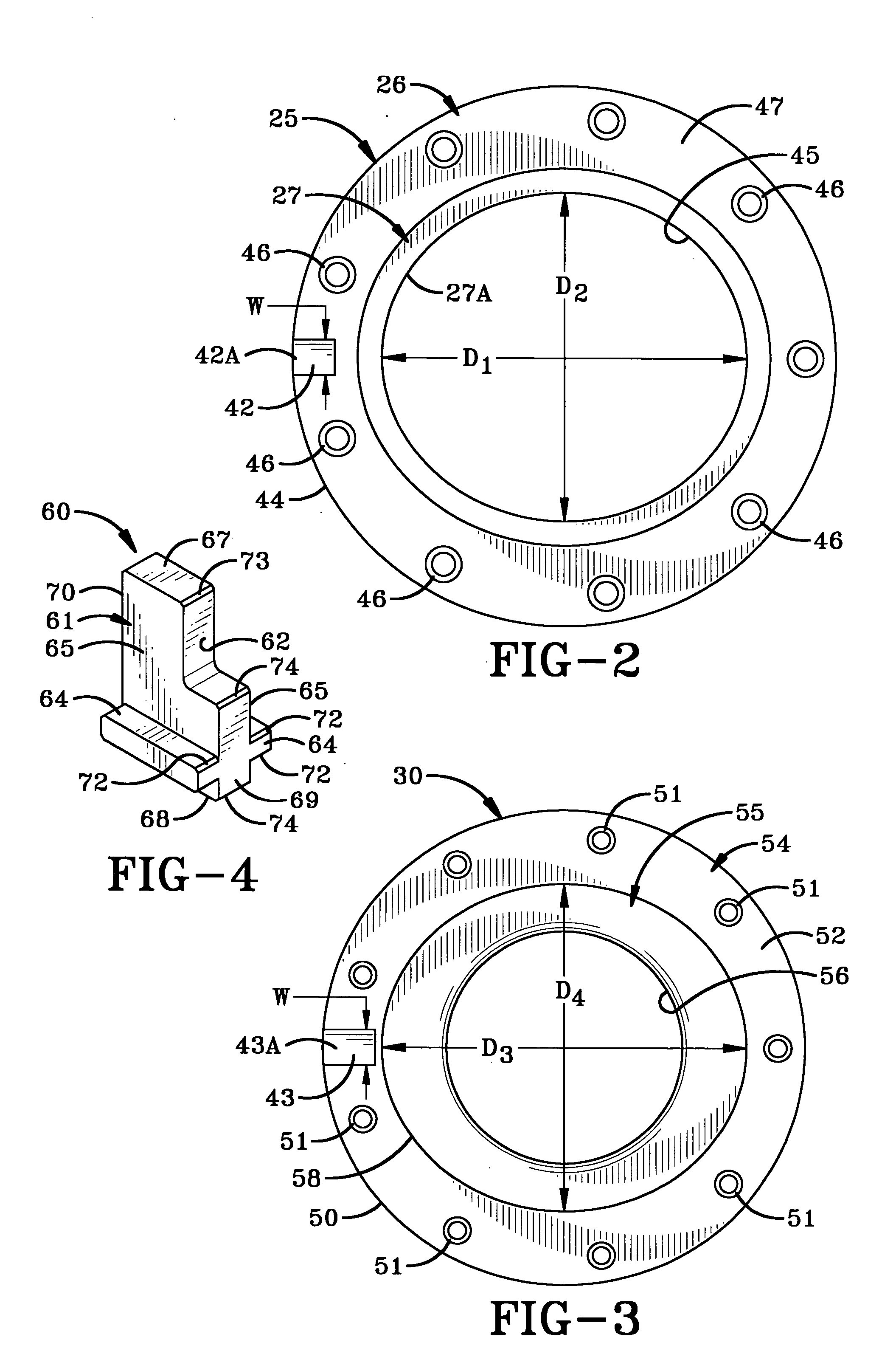
[0010] One aspect of the invention includes providing a pair of precision-shaped openings in telescopically engageable cut ring and blank and draw die, which when accurately axially aligned with the axis of the press, insures that the major and minor axii thereof are accurately aligned to enable the cut ring and blank and draw die to form non-round blank-shaped discs for subsequent forming into container components.
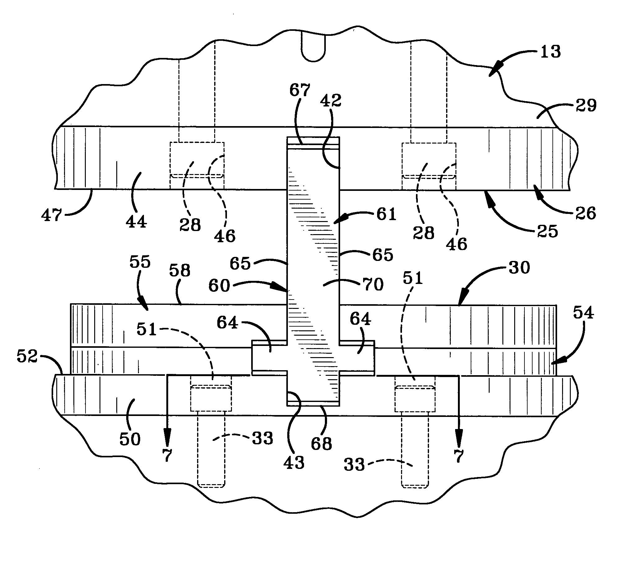
[0011] Another feature of the invention is to provide an alignment key which is slidably inserted into notches formed in the peripheries of the cut ring and blank and draw die which enables these press components to be easily adjusted into precise alignment, afterwhich securement bolts are tightened to accurately position the components in axial alignment in the press for subsequent forming of the non-round disc-shaped blanks.
[0013] A further feature of the invention is to form the alignment key with a right angled notch in one corner thereof to compensate for the difference in diameters between the cut ring and blank and draw die to facilitate the insertion of the alignment key therebetween and into the alignment notches.
[0014] A still further feature of the invention is to enable an existing press to be retrofitted easily at the press site for changing from press components which heretofore produced round disc-shaped blanks with press components for forming non-round disc-shaped blanks, without requiring elaborate setup and alignment procedures heretofore required.

Problems solved by technology

However, at various times during operation of the press, such as when a malfunction occurs, the components may become out of alignment requiring reshipment of the entire die set back to the tool and die supplier for subsequent alignment of the cut ring with the blank and draw die.

Method used


Image

  • Method and apparatus for aligning components of a press
  • Method and apparatus for aligning components of a press
  • Method and apparatus for aligning components of a press

Examples


Embodiment Construction

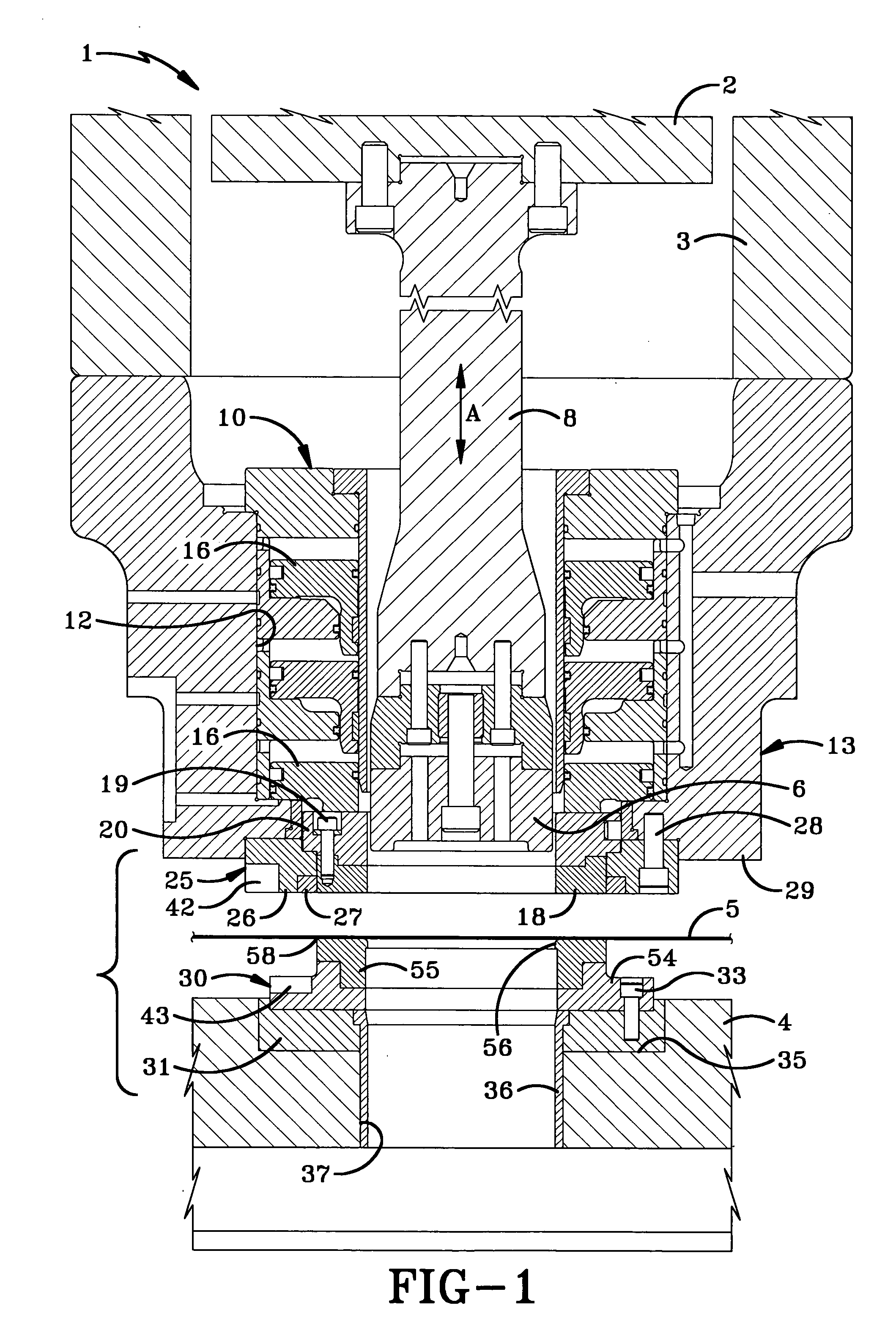
[0025]FIG. 1 illustrates one type of reciprocating press for carrying out the improved method of the present invention and which will utilize the apparatus of the present invention. Press 1 is illustrated as being a double action press and is of the type shown in U.S. Pat. Nos. 5,626,048; 5,628,224; and 5,970,775. However, other types of reciprocating presses can be utilized without affecting the concept of the invention.

[0026] Press 1 includes an inner ram 2 and an outer ram 3 movable toward and away from a generally fixed base 4 for forming disc-shaped blanks from sheet material 5. Inner ram 2 includes an inner die punch or draw horn 6 connected to a punch riser 8. Punch riser 8 will move draw horn 6 in a reciprocal vertical axial direction upon movement of inner ram 2 as shown by arrow A. A plurality of annular cylinders indicated generally at 10, are mounted in a vertical stacked relationship within an annular bore 12 of an outer ram housing 13. Pistons 16 move in unison within...


PUM

PropertyMeasurementUnit
Lengthaaaaaaaaaa
Angleaaaaaaaaaa
Diameteraaaaaaaaaa

Abstract

A method and apparatus for aligning opposed telescopically engageable cut ring and blank and draw die when mounted in a can body forming press to form non-round disc-shaped blanks which are subsequently formed into container bodies. A pair of opposed precision formed notches are formed in the peripheries of the spaced press components and a precision formed key having end portions which match the shape and size of the notches are inserted into the notches after the components have been placed in general alignment with each other in the press. Either or both of the components are then rotatably adjusted until the key is seated properly in the notches afterwhich the components are secured in the adjusted position. The key is then slidably removed from the spaced notches. Spaced ends of the key are precision formed to match the shape of the notches and a pair of stabilizing legs extend outwardly from the key to assist in aligning the key in the notches. The notches are precisely located with respect to each other and to the major and minor axii of the press components so that said major and minor axii align with each other when the key is seated in the notches.

Description

BACKGROUND OF THE INVENTION [0001] 1. Technical Field [0002] The invention relates to forming non-round disc-shaped blanks from sheet material in a forming press for subsequent formation into round container components. More particularly, the invention relates to a method and apparatus for aligning telescopically engageable press components which form the non-round blanks, namely opposed cut ring and opposed blank and draw die. Even more particularly, the invention relates to the accurate aligning of the non-round components without removing the same from the press by engagement of an accurately formed alignment key with the spaced components. [0003] 2. Background Information [0004] In the container forming art, a sheet of material, such as light-weight aluminum or steel, is fed into a press which forms a plurality of round or non-round disc-shaped blanks which are subsequently drawn into container components, such as the body and / or end shell therefor. It is known that for certain ...

Claims


Application Information

Patent Timeline
IPC IPC(8): B21D37/12B26D7/26
CPCB21D37/12B26D7/2628Y10T29/49902Y10T29/49897Y10T29/49895Y10T29/49899Y10T29/49901
Inventor MCCLUNG, JAMES A.
Owner STOLLE MACHINERY
Learn More