Honeycomb filter

Inactive Publication Date: 2005-04-14
NGK INSULATORS LTD
View PDF5 Cites 93 Cited by
  • Summary
  • Abstract
  • Description
  • Claims
  • Application Information

AI Technical Summary

Benefits of technology

[0005] The present invention has been developed in consideration of these circumstances, and an object thereof i

Problems solved by technology

When this filter is used, the pressure loss by filtering resistance has raised a problem, and there has been a demand for a filter having a small pressure loss.
In general, when the filter is used, deposits are deposited on the filter with an elapse of time, and the pressure loss increases.
Especially when the h

Method used


Image

  • Honeycomb filter
  • Honeycomb filter
  • Honeycomb filter

Examples


Embodiment Construction

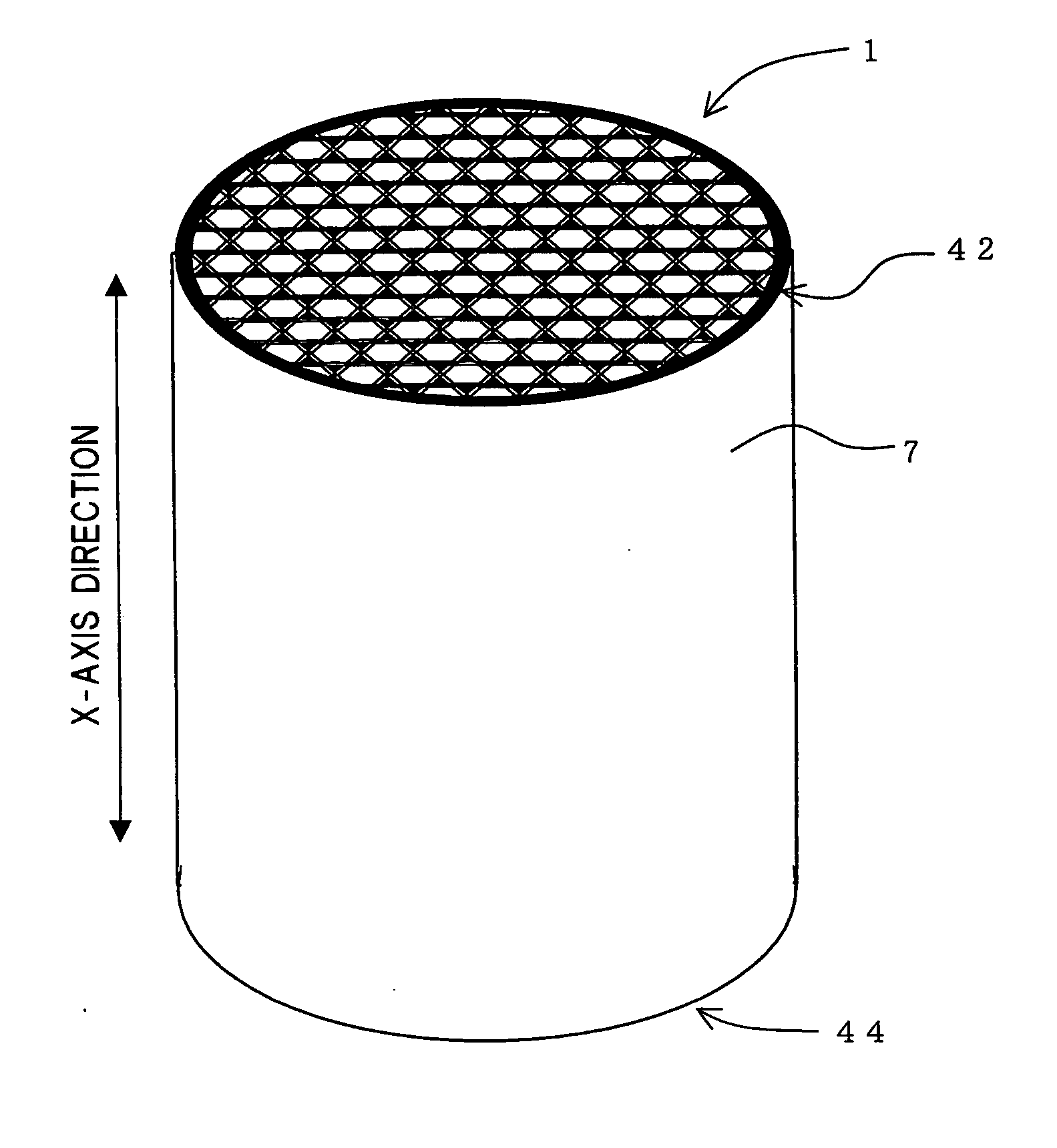
[0023] A honeycomb filter of the present invention will be described hereinafter in detail with reference to the drawings, but the present invention is not limited to the following embodiments. It is to be noted that in the following, a section means a vertical section of a through channel in a longitudinal direction (X-axis direction in FIG. 1(a)) unless especially mentioned.

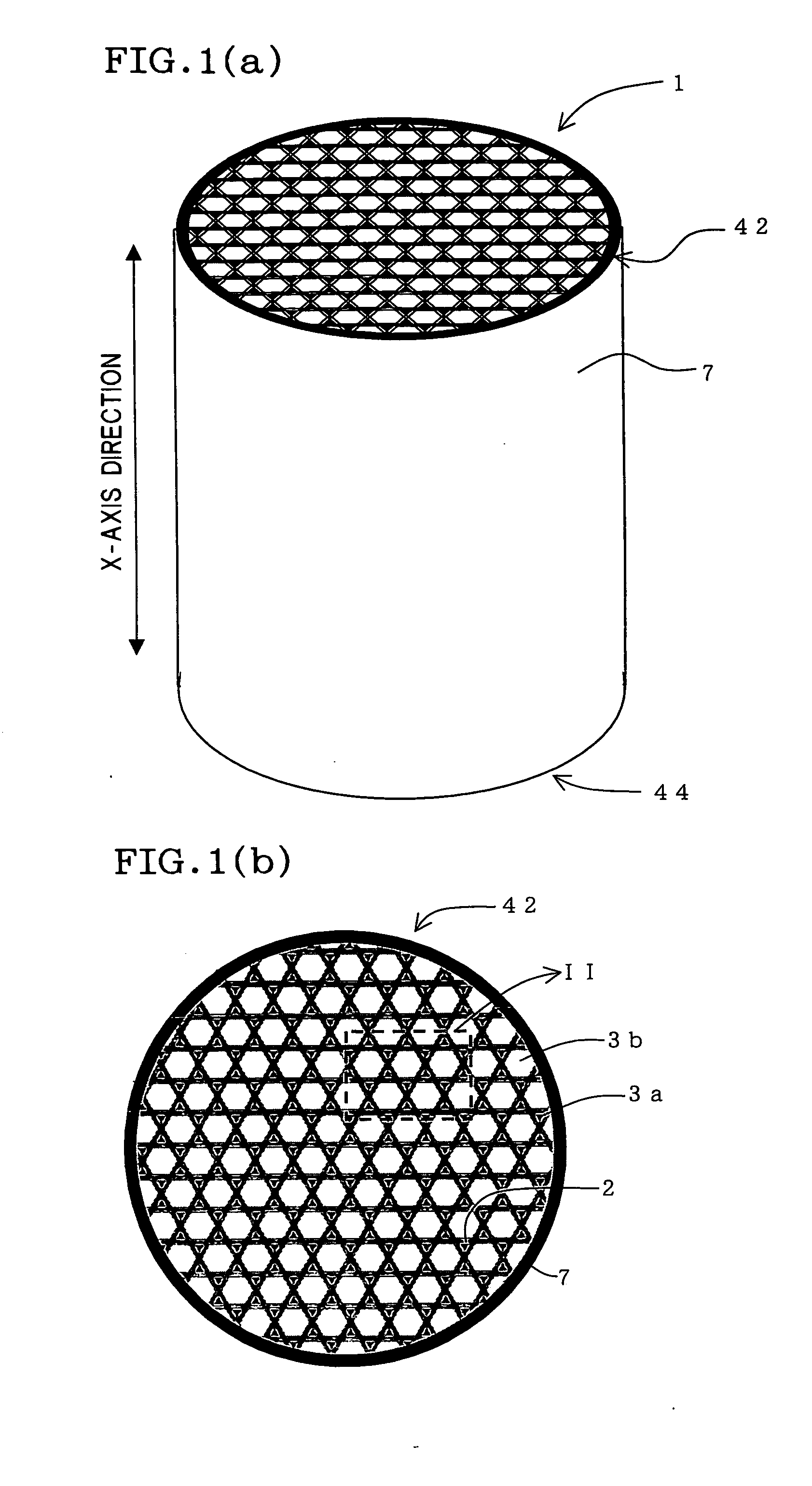
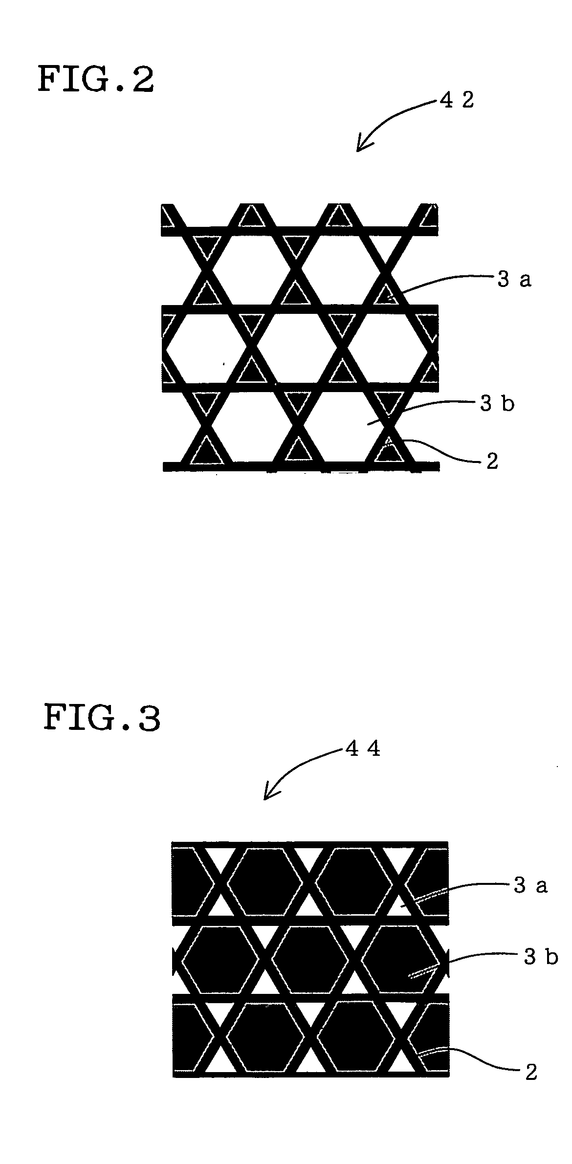
[0024] As shown in FIGS. 1(a), (b), the honeycomb filter of the present invention has: an inflow end face 42 and an outflow end face 44 of a fluid to be treated; porous partition walls 2 extending to the outflow end face 44 from the inflow end face 42; and a large number of through channels 3a and 3b partitioned by the partition walls 2 and extending through the outflow end face 44 from the inflow end face 42. Furthermore, as shown in FIGS. 2 and 3, predetermined through channels 3a are sealed in the inflow end face 42, and remaining predetermined through channels 3b are sealed in the outflow end face 44. It i...


PUM

PropertyMeasurementUnit
Porosityaaaaaaaaaa
Volumeaaaaaaaaaa
Volumeaaaaaaaaaa

Abstract

There is disclosed a honeycomb filter 1 having: an inflow end face 42 and an outflow end face 44 of a fluid to be treated; porous partition walls 2 extending to the outflow end face 44 from the inflow end face 42; and a large number of through channels 3a and 3b partitioned by the partition walls 2 and extending through the outflow end face 44 from the inflow end face 42, predetermined through channels 3a are sealed in the inflow end face, and the remaining predetermined through channels 3b are sealed in the outflow end face 44. In a case where a total of sectional areas of the through channels 3a sealed in the inflow end face 42 is A (mm2), and a total of sectional areas of the through channels sealed 3b in the outflow end face is B (mm2), a relation is A<B in the honeycomb filter 1. The honeycomb filter has only slight increase of a pressure loss with an elapse of time by the use.

Description

TECHNICAL FIELD [0001] The present invention relates to a porous honeycomb filter usable in filtering a gas, for example, to trap particulates in an exhaust gas from an internal combustion engine, a boiler and the like or in filtering liquids such as tap water / waste water, particularly to a honeycomb filter in which an increase of a pressure loss by the use is slight. BACKGROUND ART [0002] There has been an increasing need for removal of particulates or toxic substances in exhaust gases of an internal combustion engine, a boiler and the like from the exhaust gases in consideration of influences onto environments. Especially, regulations concerning the removal of particulate matters (hereinafter referred to as PM) exhausted from diesel engines have been strengthened in Western countries and Japan, and the use of a honeycomb structure filter in a trapping filter (hereinafter referred to as DPF) for removing the PM has attracted attentions. A honeycomb filter has also been used in filt...

Claims


Application Information

Patent Timeline
IPC IPC(8): F01N3/02B01D39/14B01D39/20B01D46/00B01D46/24B01D53/86B01J35/04
CPCB01D39/2068B01D46/2429B01D46/2451B01D46/2459B01D2046/2496B01D46/247B01D46/2474B01D2046/2433B01D46/2466B01D46/24491B01D46/2498B01D46/2484B01D46/2482B01D46/2478B01D39/20B01D46/00B01D39/14
Inventor ITOU, MOTOMICHIMIZUTANI, TAKASHI
Owner NGK INSULATORS LTD
Why Eureka
Try Eureka