Honeycomb structure

a honeycomb and structure technology, applied in the field of honeycomb structure, can solve the problems of low productivity, decrease of strength aspect, so as to inhibit the increase of pressure loss, improve purifying performance, and improve the effect of purification performan

Active Publication Date: 2019-04-09
NGK INSULATORS LTD
View PDF14 Cites 0 Cited by
  • Summary
  • Abstract
  • Description
  • Claims
  • Application Information

AI Technical Summary

Benefits of technology

[0009]The present invention has been developed in view of such problems, and there is provided a honeycomb structure in which it is possible to improve a purifying performance while inhibiting increase of pressure loss when using the honeycomb structure as an exhaust gas purifying catalyst carrier or filter.
[0029]In a honeycomb structure of the present invention, among a plurality of cells, the cells having open ends in a range of 1 to 80% of an area of a first end face of a honeycomb structure body are specific open cells each having such an open changing portion as described below. It is to be noted that in each of the plurality of cells excluding the cells formed at an outermost circumference, its cross-sectional shape is quadrangular or triangular. In the open changing portion of the specific open cell, a diameter D2 of an inscribed circle which comes in contact with a peripheral edge of the open end in the second end face and a diameter D1 of an inscribed circle which comes in contact with a peripheral edge of the open end in the first end face satisfy a relation of 1≤|(1−(D1 / D2))×100|≤80. Furthermore, in this open changing portion of the specific open cell, the diameter D2 of the inscribed circle and a diameter D3 of an inscribed circle which comes in contact with a peripheral edge of the cell in a cross section perpendicular to a direction from the first end face toward the second end face satisfy a relation of 1≤|(1−(D3 / D2))×100|≤80 in a range of a part of 20 mm or less from the first end face. Further, this open changing portion of the specific open cell is present only in a range of the specific open cell which is 20 mm or less from the first end face. When using the honeycomb structure of the present invention having such a constitution as an exhaust gas purifying catalyst carrier or filter, it is possible to improve a purifying performance while inhibiting increase of pressure loss. Furthermore, in the honeycomb structure of the present invention, the open changing portion in which a size of the open end of the specific open cell changes is present only in the range of 20 mm or less from the first end face, and hence it is possible to improve the purifying performance while remarkably effectively inhibiting the increase of the pressure loss. Furthermore, in the honeycomb structure of the present invention, its manufacturing is comparatively simple and contributes to improvement of productivity.

Problems solved by technology

Consequently, it is possible to improve a purifying performance by an interaction between an exhaust gas and each partition wall, but there has been the problem that increase of pressure loss is remarkably large.
Furthermore, in the above-mentioned corrugated wall honeycomb structure or the like, wall surface portions of the partition walls are formed into the corrugated shape along the whole surface and total length of the honeycomb structure, and hence there is the fear that decrease of a strength aspect might occur.
Furthermore, in such a corrugated wave honeycomb structure or the like, its manufacturing method is laborious, and hence there has been the problem that productivity is low and manufacturing cost noticeably increases.

Method used


Image

  • Honeycomb structure
  • Honeycomb structure
  • Honeycomb structure

Examples


example 1

[0140]To 100 parts by mass of cordierite forming raw material, there were added 0.5 part by mass of pore former, 33 parts by mass of dispersing medium and 5.6 parts by mass of organic binder, respectively, followed by mixing and kneading to prepare a kneaded material. As the cordierite forming raw material, there were used alumina, aluminum hydroxide, kaolin, talc, and silica. Water was used as the dispersing medium, a water absorbable polymer having an average particle diameter of 10 to 50 μm was used as the pore former, methylcellulose was used as the organic binder, and dextrin was used as a dispersing agent.

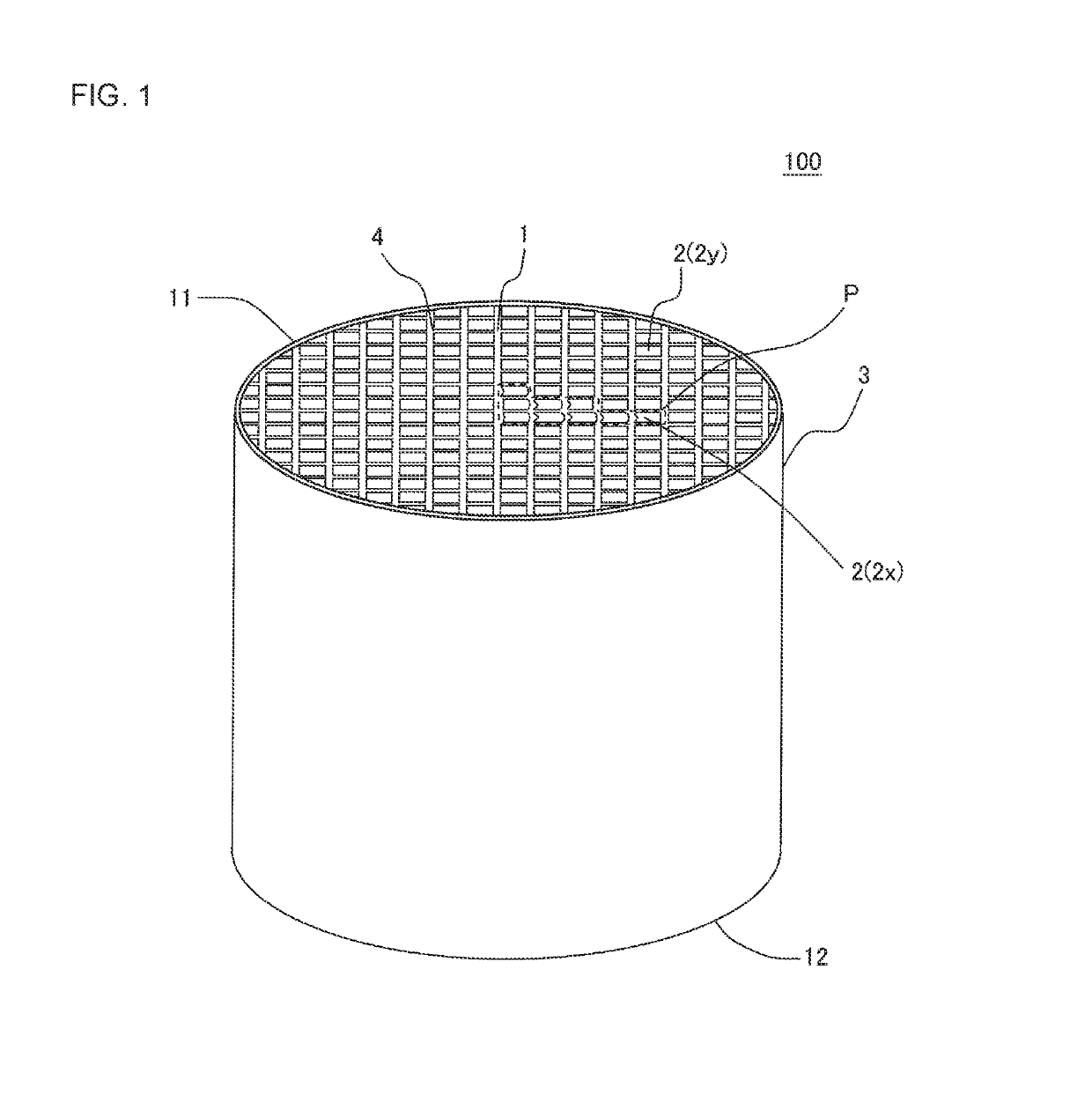
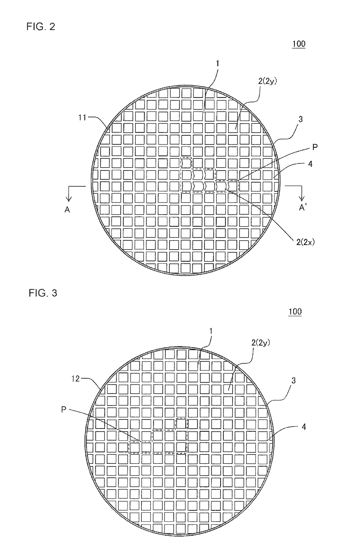
[0141]Next, the kneaded material was extruded by using a predetermined die, to obtain a honeycomb formed body in which a cell shape was quadrangular and the whole shape was a round pillar shape.

[0142]Next, the honeycomb formed body was mounted on a fired setter made of alumina so that a first end face of a honeycomb structure to be prepared was directed downward. As the fired...

examples 2 to 18

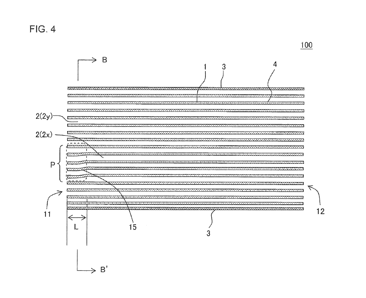
[0165]In Examples 2 to 18, the procedure of Example 1 was repeated except that a cell structure, a porosity, a cross-sectional shape, a diameter, a long diameter, a short diameter and a total length were changed as shown in Table 1 and further except that a firing method was changed as follows in each of Examples 2 to 18, to prepare honeycomb structures. Here, “the long diameter” is the longest straight line among straight lines each connecting two points on a circumferential edge of a cross section of the honeycomb structure which is perpendicular to a cell extending direction. Further, “the short diameter” is a straight line perpendicular to the above “long diameter” in the cross section perpendicular to the cell extending direction. In Example 14, the cross-sectional shape of the honeycomb structure was elliptic, the long diameter was 228.6 mm, and the short diameter was 137.2 mm. In Example 15, the cross-sectional shape of the honeycomb structure was elliptic, the long diameter ...


PUM

PropertyMeasurementUnit
diameter D3Xaaaaaaaaaa
diameter D2aaaaaaaaaa
thicknessaaaaaaaaaa

Abstract

A honeycomb structure having a quadrangular or triangular cross-sectional shape of cells and having specific open cells in which open changing portions are present only in a range of 20 mm or less from the first end face, and the open changing portion satisfies relations of 1≤|(1−(D1 / D2))×100|≤80 and 1≤|(1−(D3 / D2))×100|≤80. D1 indicates a diameter of an inscribed circle which comes in contact with a peripheral edge of the open end of the cell in the first end face. D2 indicates a diameter of the inscribed circle which comes in contact with the peripheral edge of the open end of the cell in the second end face. D3 indicates a diameter of an inscribed circle which comes in contact with a peripheral edge of the cell in a cross section perpendicular to a direction from the first end face toward the second end face.

Description

[0001]“The present application is an application based on JP-2016-007765 filed on Jan. 19, 2016 with Japan Patent Office, the entire contents of which are incorporated herein by reference.”BACKGROUND OF THE INVENTIONField of the Invention[0002]The present invention relates to a honeycomb structure. More particularly, it relates to a honeycomb structure in which it is possible to improve a purifying performance while inhibiting increase of pressure loss when using the honeycomb structure as an exhaust gas purifying catalyst carrier or filter.Description of the Related Art[0003]Honeycomb structures are broadly used in a catalyst carrier, a filter and the like, and are broadly used especially as a catalyst carrier, a filter and the like to purify or treat exhaust gases from internal combustion engines such as a gasoline engine and a diesel engine, and a burning device. Here, the honeycomb structure is a structure in the form of a honeycomb which includes porous partition walls defining...

Claims


Application Information

Patent Timeline
Patent Type & Authority Patents(United States)
IPC IPC(8): F01N3/28F01N3/022B01D46/24B01D53/94
CPCF01N3/0222B01D46/247B01D53/9445F01N3/2828F01N3/2842Y02T10/20B01D2046/2481B01D2046/2496B01D2279/30F01N2330/34B01D2046/2477B01J32/00B01D39/14B01D39/2068B01D46/00B01D46/0001B01D46/2418B01D53/86B01D53/88C04B38/0009B01D2258/012B01D2258/01B01D46/249B01D46/2488B01D46/2484B01D46/2482B01D46/2476Y02T10/12B01D46/2498B01D46/2451B01D46/2474
Inventor MATSUYA, JUNKIKATO, YASUSHIKONDO, TAKAHIRO
Owner NGK INSULATORS LTD
Why Eureka
Try Eureka