
Honeycomb structure

a honeycomb and structure technology, applied in the field of honeycomb structure, can solve the problems of affecting the efficiency of honeycomb structure, and difficult to discharge ash accumulated from the honeycomb structure, etc., to inhibit the increase of pressure loss and excellent trapping efficiency

Inactive Publication Date: 2015-08-27
NGK INSULATORS LTD
View PDF2 Cites 0 Cited by
  • Summary
  • Abstract
  • Description
  • Claims
  • Application Information

AI Technical Summary

Benefits of technology

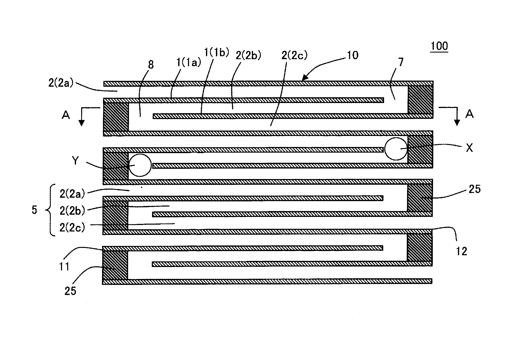
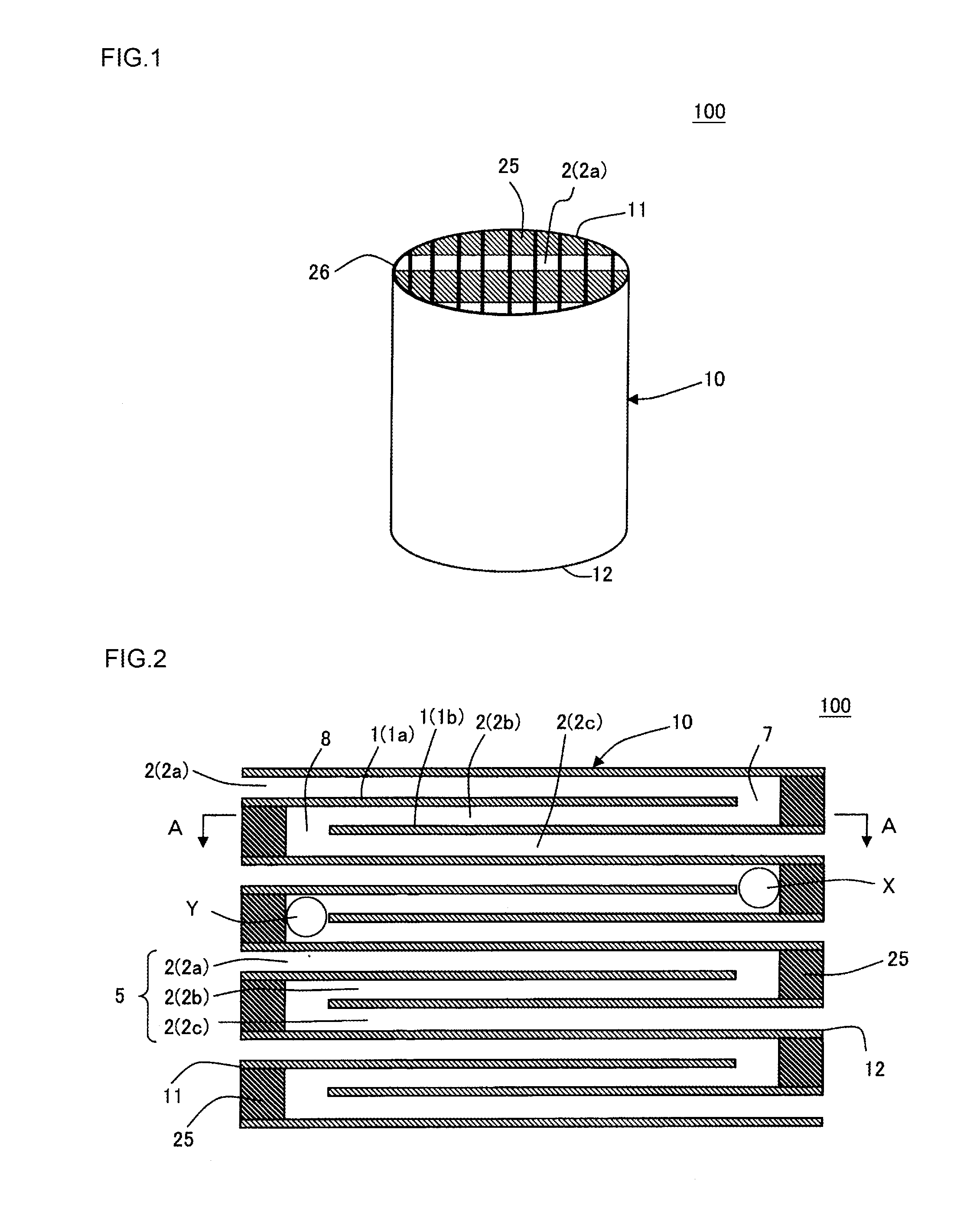
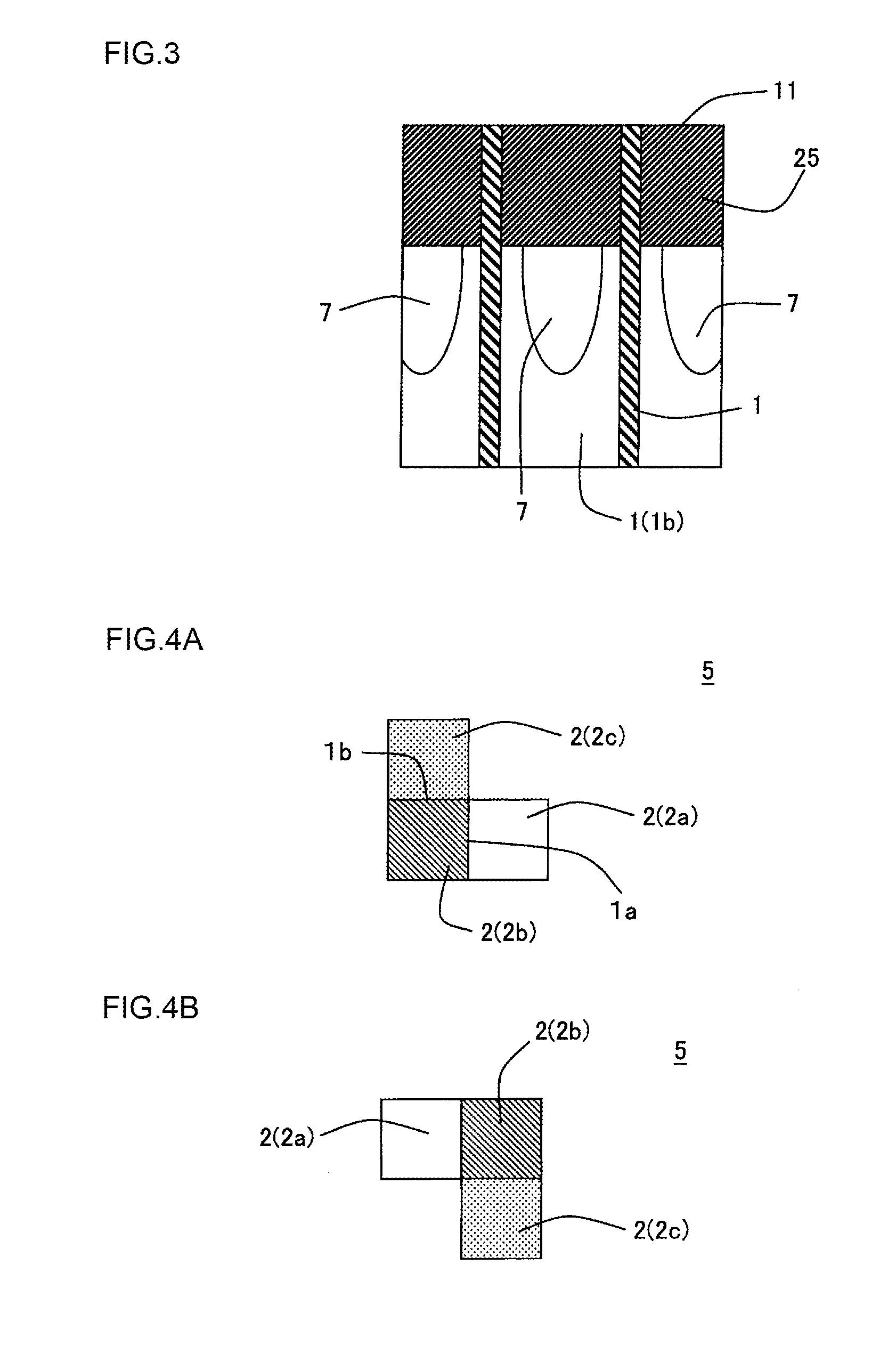
The present invention provides a honeycomb structure with a favorable trapping efficiency and inhibits increase of pressure loss when ash is accumulated. The structure has cell groups with specific cells and flow-through holes, allowing ash to be trapped at two positions. The accumulated ash joins the exhaust gas flow and is discharged outside, reducing the need for maintenance. Overall, the honeycomb structure is "free of maintenance" regarding ash deposition.

Problems solved by technology

However, in honeycomb structures described in Patent Documents 1 and 2, one open end or the other open end of each cell is plugged, and hence pressure loss noticeably increases.
Furthermore, when ash which is a noncombustible substance included in PM is accumulated, such accumulated ash is hard to be discharged from the honeycomb structure.
Therefore, the pressure loss when ash is accumulated also noticeably increases.
However trapping efficiency of PM is deteriorated.
In a honeycomb structure described in Patent Document 4, similarly to Patent Document 3, there are cells in which no plugging portion is disposed, and hence the pressure loss increase is low, however as compared with the honeycomb structures described in Patent Documents 1 and 2, the trapping efficiency of PM is deteriorated.
Ash deposited in this portion is hard to be discharged.
In consequence, when the deposited ash is not discharged, the pressure loss disadvantageously increases.
On the other hand, a great deal of labor is required to discharge ash.

Method used


Image

  • Honeycomb structure
  • Honeycomb structure
  • Honeycomb structure

Examples


example 1

[0106]A pore former, an organic binder and water were added to a cordierite forming raw material to obtain a forming raw material. The forming raw material was mixed and kneaded to prepare a columnar kneaded material. As an organic binder, methylcellulose was used, and 5 parts by mass of methylcellulose was added to 100 parts by mass of the cordierite forming raw material. The water was added as a dispersing medium as much as 10 mass % to the whole forming raw material. The cordierite forming raw material is a raw material which becomes cordierite when fired. Specifically, the cordierite forming raw material is a ceramic raw material obtained by mixing “predetermined raw materials” to obtain a chemical composition in which silica (SiO2) is in a range of 42 to 56 mass %, alumina (Al2O3) is in a range of 30 to 45 mass %, and magnesia (MgO) is in a range of 12 to 16 mass %. “The predetermined raw materials” are raw materials selected from the group consisting of talc, kaolin, calcinate...


PUM

PropertyMeasurementUnit
thicknessaaaaaaaaaa
thicknessaaaaaaaaaa
thicknessaaaaaaaaaa

Abstract

Provided is a honeycomb structure including a honeycomb substrate having partition walls defining cells extending from an inflow end face to an outflow end face, and plugging portions. The cells include at least one cell group consisting of a both-end plugged cell, an inlet cell adjacent to the both-end plugged cell, and an outlet cell adjacent to the both-end plugged cell. The partition walls defining the both-end plugged cell have a first common partition wall defining both of the inlet cell and the both-end plugged cell, and a second common partition wall defining both of the outlet cell and the both-end plugged cell. A first flow-through hole is formed in an end portion of the first common partition wall on the outflow end face side, and a second flow-through hole is formed in an end portion of the second common partition wall on the inflow end face side.

Description

[0001]The present application is an application based on JP-2014-033448 filed on Feb. 24, 2014 with the Japanese Patent Office, the entire contents of which are incorporated herein by reference.BACKGROUND OF THE INVENTION[0002]1. Field of the Invention[0003]The present invention relates to a honeycomb structure, and more particularly, relates to a honeycomb structure which is excellent in trapping efficiency and inhibits an increase of pressure loss when ash is accumulated.[0004]2. Background Art[0005]Heretofore, for the purpose of removing particulates (hereinafter also referred to as PM (Particulate Matter)) included in exhaust gas discharged from various engines and the like, exhaust gas purifying devices including honeycomb structure filter (honeycomb structure) have been used. There is known a honeycomb structure including a honeycomb structured honeycomb substrate and plugging portions disposed at open ends of inlet cells which are predetermined cells of this honeycomb substra...

Claims


Application Information

Patent Timeline
Patent Type & Authority Applications(United States)
IPC IPC(8): F01N3/022
CPCF01N3/0222F01N2330/48Y02T10/12
Inventor YAMADA, TOSHIOHIROSE, SHOGOHIRAKAWA, TOSHIHIRO
Owner NGK INSULATORS LTD
Learn More