Run-flat core

a core and tire technology, applied in the field of cores, can solve the problems of low tire manufacturing energy, no interchangeability, and low use of methods, and achieve the effect of facilitating the insertion of the core into the tir

Inactive Publication Date: 2005-04-14
TOPY INDUSTRIES
View PDF10 Cites 27 Cited by
  • Summary
  • Abstract
  • Description
  • Claims
  • Application Information

AI Technical Summary

Benefits of technology

An object of the present invention is to provide a run-flat core wherein the core is lighter, insertion of the core into a tire is easier, and pressing the core to a wheel rim is easier, than in the above-described type C structure.

Problems solved by technology

As a result, a tire manufacturing energy is decreased.
However, those methods are not widely used for the following reasons: There is no interchangeability with a usual non-run-flat tire.
The number of parts is relatively large, accompanied by an increase in cost.
Mounting and dismounting of the tire and core onto the wheel is difficult.
However, those methods are not widely used for the following reasons: If an aspect ratio of a tire is high, a run-flat ability is not obtained.
Due to the reinforcing of the side wall, the spring characteristic of the vehicle in a vertical direction becomes rigid, so that riding comfort is degraded and noise increases.
Due to the reinforcing of the side wall, absorption of shocks in a vertical direction is decreased, which affects the strength of the vehicle.
Since a reinforced side wall has little flexibility, mounting and dismounting of the tire to the wheel is difficult.
However, the above-described type C structure has the following problems: (1) In the proposed structure, the core is heavy.
(2) The size of the core is large and the cost for manufacturing and conveying the core is high.
Further, insertion of the core into the tire is difficult.
(3) Pressing the core to a wheel rim is difficult, because the core is likely to float up from the rim due to centrifugal force.

Method used


Image

  • Run-flat core
  • Run-flat core
  • Run-flat core

Examples


Embodiment Construction

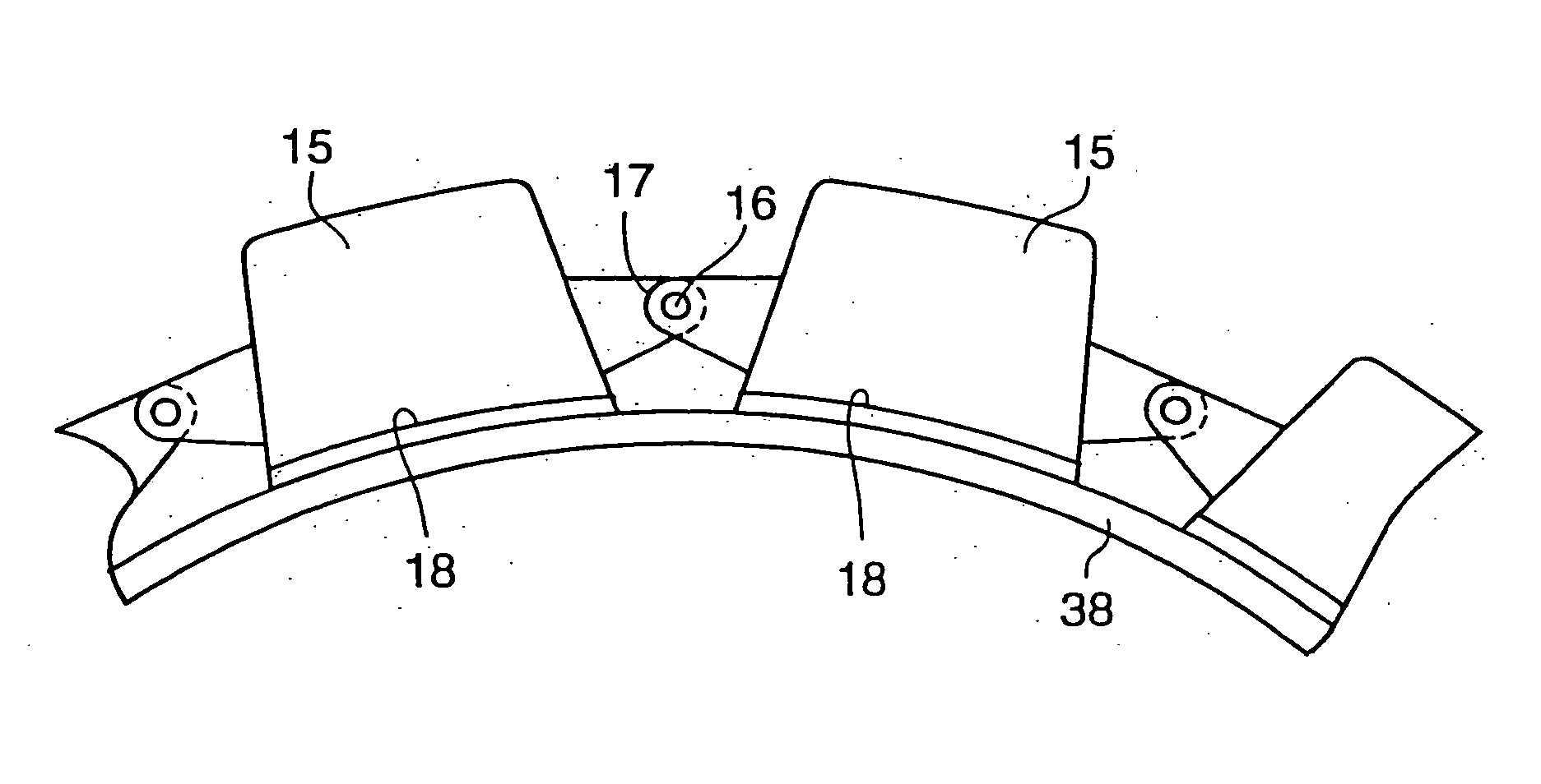
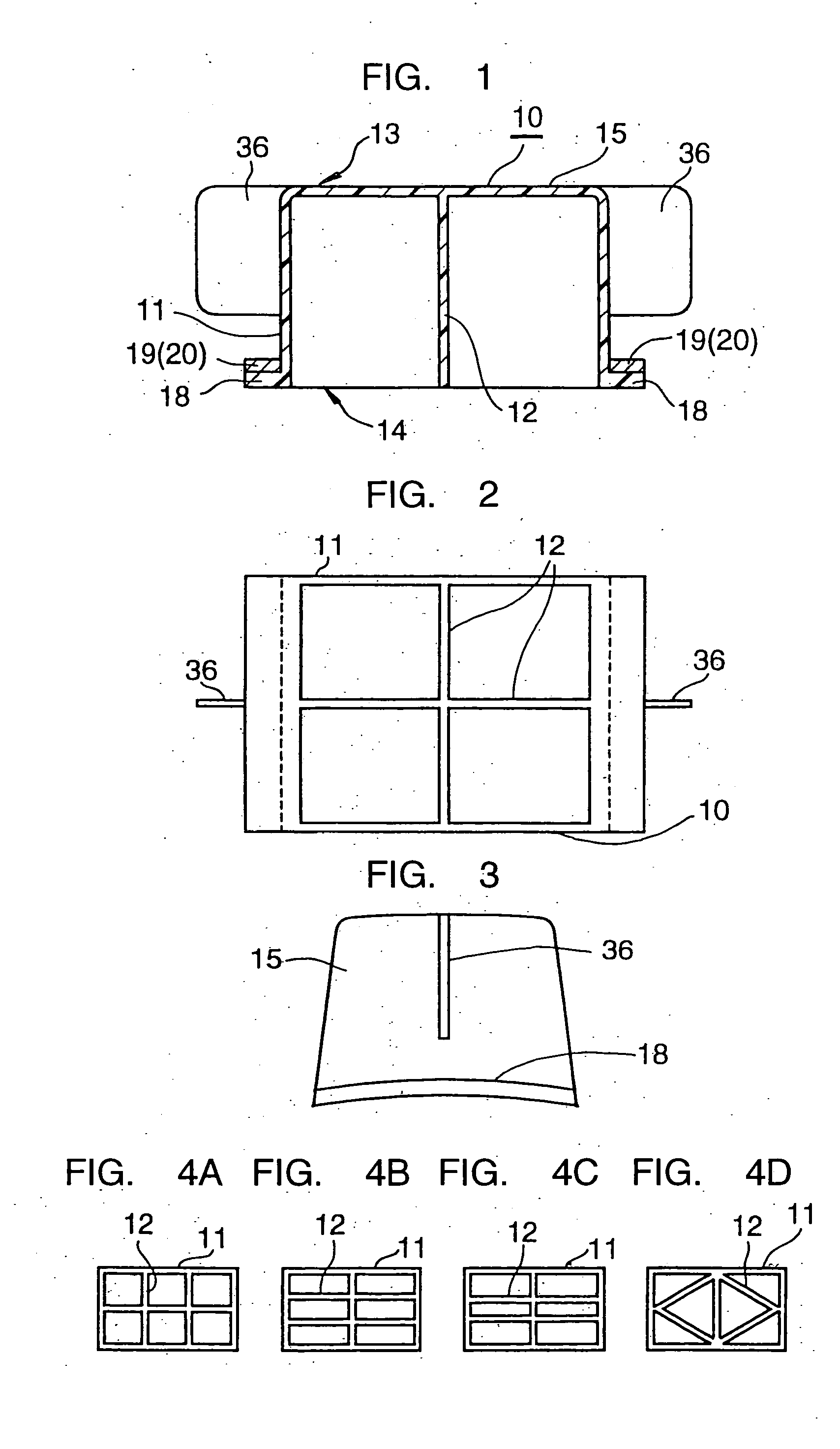
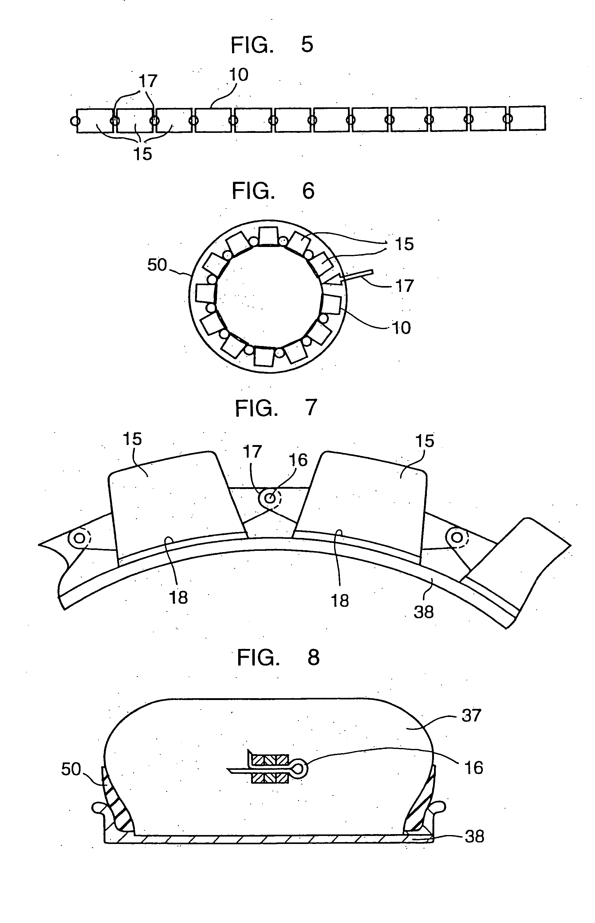
Various embodiments of run-flat cores will be explained with reference to FIGS. 1-37. First structures for solving the above-described problems (1), (2) and (3) will be explained in items (1), (2) and (3) below, respectively, and second structures as an extension of the first structures will be explained in item (4) below. Further, third structures which are improvements of the second structures will be explained in item (5) below.

(1) Lightening of the Core

In order to lighten the core, low density material is used for the core and material is removed from unnecessary portions. A core of the above-described C structure has a volume of about 0.8 L (L: liter) per one protruded portion (a portion between adjacent notches). When the density of the material of the protruded portion is about 1 g / cc, the weight of the protrusion is about 0.8 kg, and the weight of all of the protrusions is about 10 kg. The core is too heavy. To solve the problem, the material of the core can be changed ...


PUM


Abstract

A run-flat core has a closed upper surface and an open lower surface and includes a reinforcement plate provided for reinforcement within the core. The core includes one or more blocks formed in the same shape with each other and connected in a circumferential direction of a wheel. The core has flanges protruding in right and left directions at a lower portion of the core. A band is wound onto the flanges, and by tensioning the band, the core is pressed to a rim. The blocks are connected to each other at a lower portion of the core. The core may include a longitudinal groove, and by winding the band onto the longitudinal groove, the core is pressed to the rim.

Description

FIELD OF THE INVENTION The present invention relates to a core housed inside a tire and fastened to a wheel rim so that even when the tire is punctured (so that it becomes flat), the core supports the tire from inside to thereby cause a vehicle to be able to run further than it could without the core (hereinafter, a run-flat core). BACKGROUND OF THE INVENTION A run-flat tire is being developed from the following two viewpoints: (1) A spare tire can be omitted, accompanied by the following advantages: Economy of energy: The weight of a vehicle is decreased and fuel economy is improved. As a result, a tire manufacturing energy is decreased. Space-saving: The spare tire mounting space is available for other use. Decrease in cost: The spare tire, the wheel for mounting the tire, the tool associated with the spare and the jack can be omitted. (2) Security of a driver is assured, accompanied by the following advantages: A driver is not exposed to crime or other danger because the ...

Claims


Application Information

Patent Timeline
Patent Type & Authority Applications(United States)
IPC IPC(8): B60C17/04
CPCB60C17/04B60C17/041B60C17/10B60C2019/006B60C17/00
Inventor KIMURA, YOSHIAKIITO, TAKAHIKOKAINOSE, TAKASHISETO, MASAHIRO
Owner TOPY INDUSTRIES
Why Eureka
Try Eureka