Pneumatic tire

a technology of pneumatic tires and axles, which is applied in the field of pneumatic tires, can solve the problems of large variations of tire axle force and noise, and achieve the effect of reducing the variations of tire axle force and high precision

Inactive Publication Date: 2005-04-14
BRIDGESTONE CORP
View PDF3 Cites 19 Cited by
  • Summary
  • Abstract
  • Description
  • Claims
  • Application Information

AI Technical Summary

Benefits of technology

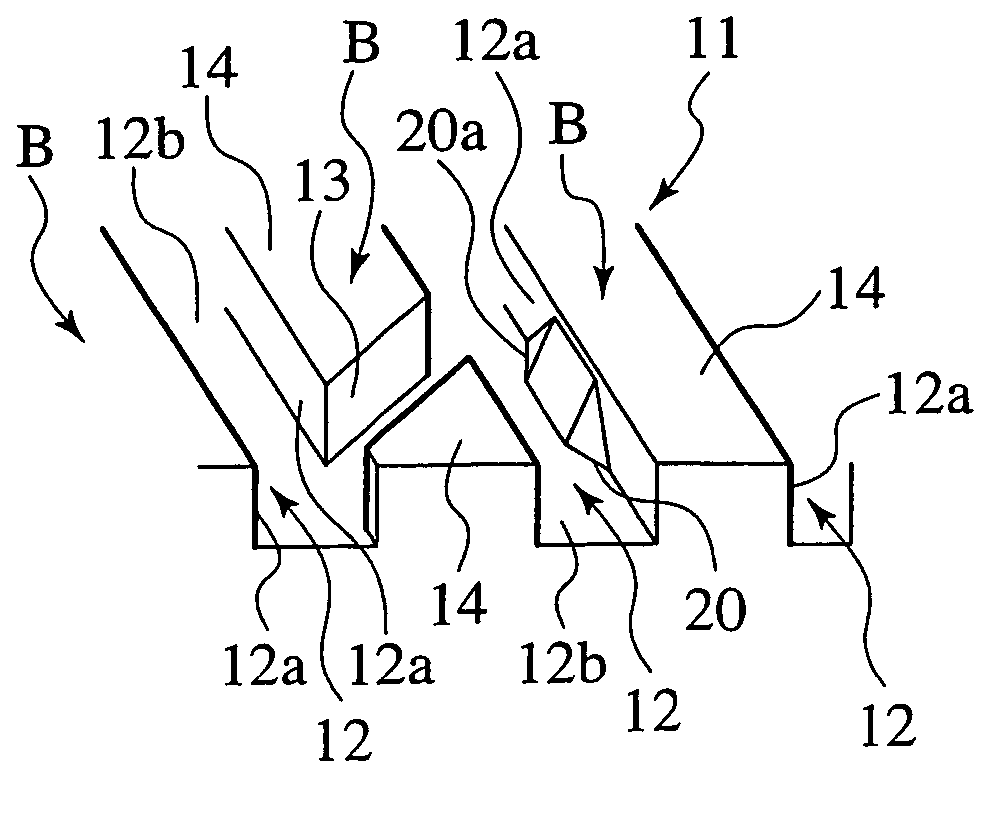
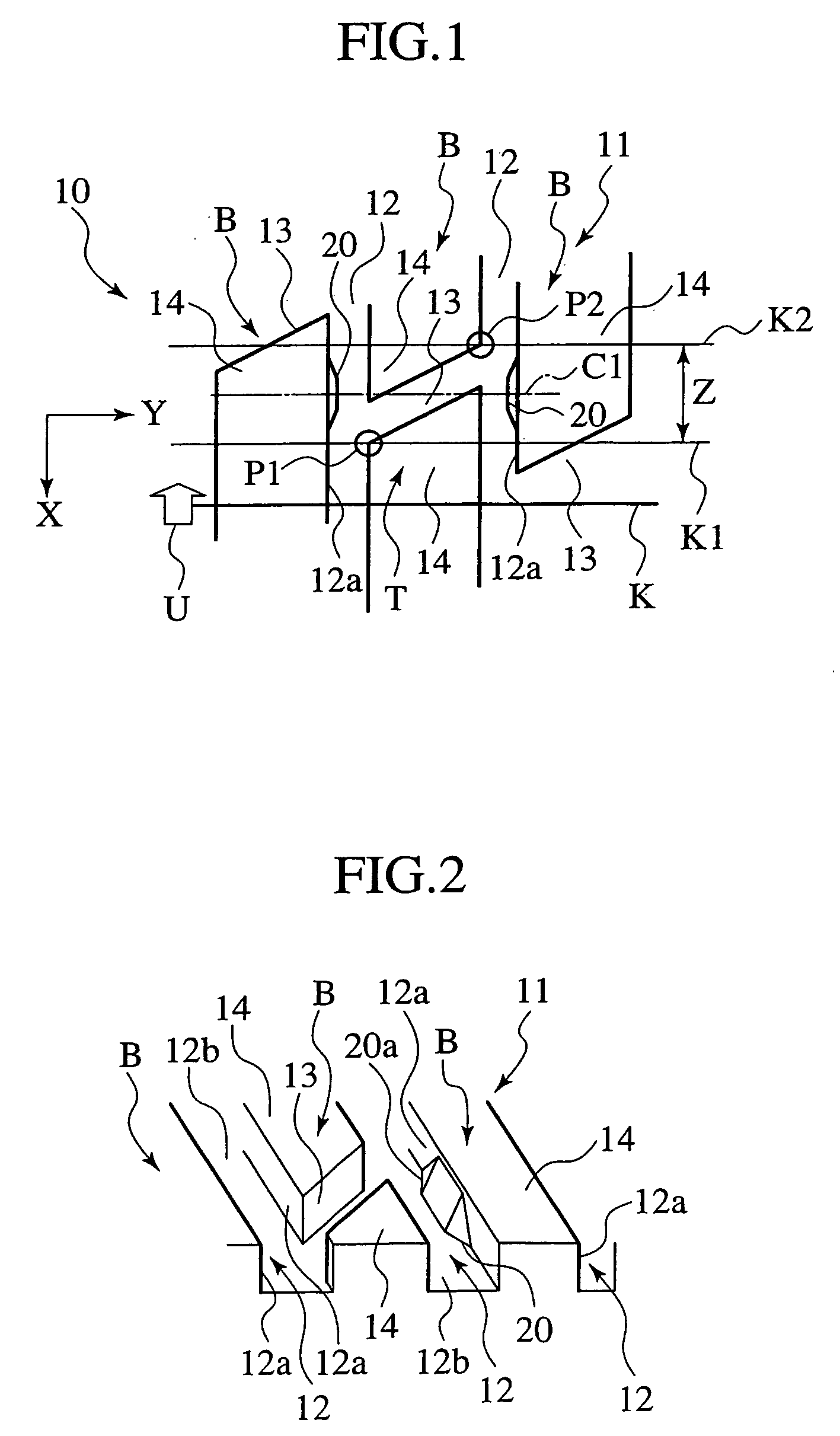
[0009] In this case, when the discontinuous portions formed in the rib lines reach a footprint line as the tire rotates, though the tire axle force is varied by these discontinuous portions, the variations of the tire axle force can be canceled by the rigidity changing portions provided in the rib groove. Therefore, the variations of the tire axle force, which are caused by the discontinuous portions, are restricted by the rigidity changing portions, and eventually, vibrational force to an axle is lowered, and pattern noise caused thereby can be reduced effectively.
[0010] Moreover, the rigidity changing portions, which cancel the variations of the tire axle force caused by the discontinuous portions, are provided in the rib groove, and thus these rigidity changing portions do not jut from a surface of the tire. Accordingly, even in the case where the rigidity changing portions are located within a region of the tread surface portion, the surface of the tire can be grounded smoothly.
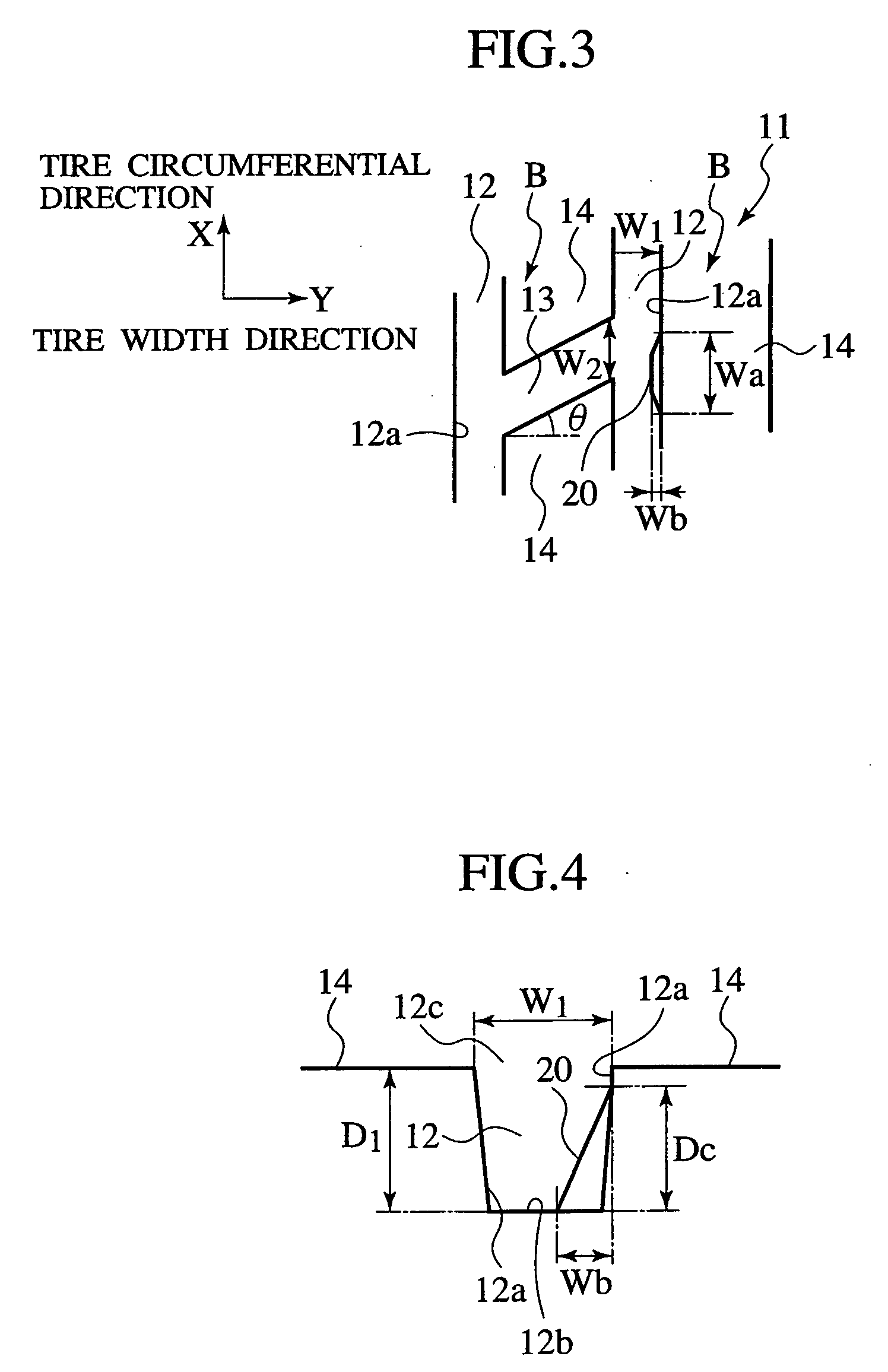
[0014] In this case, the protruding portions are formed on the wall surface of the rib groove, and thus, in portions where the protruding portions are formed, the rib lines are amplified in a tire width direction, and rigidity can be easily increased. When the portions where the rigidity is increased are grounded, the rigidity against the tread compression is increased. In this case, the rigidity changing portions can be formed into a simple structure in which the wall surface of the rib groove is protruded.
[0020] In this case, the discontinuous portions and the rigidity changing portions are simultaneously present on the footprint line of the tire, and accordingly, at the same timing (moment) when the portions discontinuous in terms of the rigidity contact the road surface, the portions where the rigidity changing portions are formed are also grounded, and the tire axle force varying in the portions discontinuous in terms of the rigidity can be canceled with high precision.
[0021] An invention of claim 6 is the pneumatic tire according to any one of clams 1 to 5, characterized in that the rigidity changing portions are provided to correspond to every predetermined number of the discontinuous portions. Also in this case where the rigidity changing portions are made to correspond to every predetermined number of the discontinuous portions, the total number of rigidity changing portions to be formed can be reduced without significantly lowering an effect of reducing the variations of the tire axle force in the tire as a whole.

Problems solved by technology

However, among problematic phenomena in the noise caused by such a pattern of the tire, there is noise heard in a vehicle cabin during vehicle running (hereinafter, referred to as “pattern noise”).
Then, a load is lowered to a great extent, leading to great variations of the tire axle force.

Method used


Image

  • Pneumatic tire
  • Pneumatic tire
  • Pneumatic tire

Examples


embodiments

[0058] (Embodiments)

[0059] Based on the basic constitution of the pneumatic tire 10 described above, specific pneumatic tires 10a to 10 g will be disclosed by first to seventh embodiments shown in FIGS. 8 to 14.

first embodiment

[0060] (First embodiment)

[0061]FIG. 8 is a bottom view showing a tread portion 11 of the pneumatic tire 10a of the first embodiment of the present invention. The same reference numerals will be added to the same constituent portions as those of the basic structure, and duplicate description will be omitted. Then, the first embodiment will be described.

[0062] In the tread portion 11 of the pneumatic tire 10a of this first embodiment, three rib lines B1, B2 and B3 are provided on a center portion in the tire width direction Y, and wide rib lines B4 and B5 are provided on both shoulder portions (both-side portions in the width direction Y).

[0063] In this case, with regard to the three rib lines B1, B2 and B3 on the center portion, the rib line B1 is referred to as a center rib, and the rib lines B2 and B3 are referred to as second ribs. Moreover, the rib lines B4 and B5 on both shoulder portions are referred to as shoulder ribs. As a matter of course, the respective rib lines B1, B2,...

second embodiment

[0069] (Second Embodiment)

[0070]FIG. 9 is a bottom view showing a tread portion 11 of the pneumatic tire 10b of the second embodiment of the present invention. The same reference numerals will be added to the same constituent portions as those of the first embodiment, and duplicate description will be omitted. Then, the second embodiment will be described.

[0071] On the tread portion 11 of the pneumatic tire 10b of this second embodiment, the same number of rib grooves 12 and lug grooves 13 in the same shape as those of the first embodiment are formed, and on each of the rib lines B1, B2, B3, B4 and B5, sixty blocks 14 are provided in the tire circumferential direction X.

[0072] Here, in this second embodiment, the protruding portions 20 are alternately provided for the respective lug grooves 13 of each of the rib lines B1, B2, B3, B4 and B5, and thirty protruding portions 20 which are a half of the blocks 14 in number are provided in the tire circumferential direction X of each wal...


PUM


Abstract

A pneumatic tire 10, in which at least one rib groove 12 extended in a tire circumferential direction is formed on a tread surface portion T of a tread portion 11, and portions 13 discontinuous in terms of rigidity are formed in a circumferential direction of rib lines B formed by the rib groove 12, the discontinuous portions 13 causing variations of tire axle force. Rigidity changing portions 20 which cancel the variations of the tire-axle force are provided in the rib groove 12, the variations being caused by the discontinuous portions 13. Thus, vibrational force to an axle is lowered, and pattern noise caused thereby is reduced effectively.

Description

TECHNICAL FIELD [0001] The present invention relates to a pneumatic tire in which portions discontinuous in terms of rigidity are formed in a circumferential direction of rib lines formed by a rib groove, the discontinuous portions causing variations of tire axle force. Particularly, the present invention relates to a pneumatic tire made to reduce noise in a vehicle cabin, which is caused by the discontinuous portions. BACKGROUND ART [0002] In a pneumatic tire such as a radial tire mounted on a vehicle such as an automobile, a tread portion is formed in order to enhance a grip performance on a road surface. This tread portion is constituted in a manner that a plurality of rib grooves extended in a tire circumferential direction (grooves in the circumferential direction) are formed on a tread surface portion in contact with the road surface to form a plurality of rib lines, that a large number of lug grooves extended in a tire width direction (lateral grooves) are further formed on t...

Claims


Application Information

Patent Timeline
Patent Type & Authority Applications(United States)
IPC IPC(8): B60C11/04B60C11/00B60C11/11B60C11/117B60C11/13
CPCB60C11/0318B60C11/11Y10S152/902B60C2011/1338B60C11/13B60C11/0309B60C11/1323
Inventor SAGUCHI, TAKANARI
Owner BRIDGESTONE CORP
Why Eureka
Try Eureka