Elevator device for a multi-sky-lobby system

Active Publication Date: 2005-04-14
OTIS ELEVATOR CO
View PDF21 Cites 41 Cited by
  • Summary
  • Abstract
  • Description
  • Claims
  • Application Information

AI Technical Summary

Benefits of technology

[0041] The space required by the entire elevator system can be reduced. If the space is 100% in the design of a conventional zone system, then the space required by the system of the present invention will be 65-70%.
[0042] It is possible to reduce the maximum space occupied on each floor. If the space is 100% in the design of a conventional zone system, the space required by the system of the present invention will be 60-65%.
[0043] It is possible to reduce the necessary total

Problems solved by technology

Consequently, the area of the elevator shaft of the express zone of the higher bank (express region) becomes larger, and this affects the overall space of the elevator.
Also, the space of the elevator shaft for each floor in the direction of the lower bank also becomes larger, so that the effective space for construction of the lower floors decreases, which is undesirable.
As a result, the required capacity of the motor (hoisting devices) increases, and, since they are operated at high speed, the noise level also increases, which is undesirable.
Also, a long time is required to mo

Method used


Image

  • Elevator device for a multi-sky-lobby system
  • Elevator device for a multi-sky-lobby system
  • Elevator device for a multi-sky-lobby system

Examples


Example

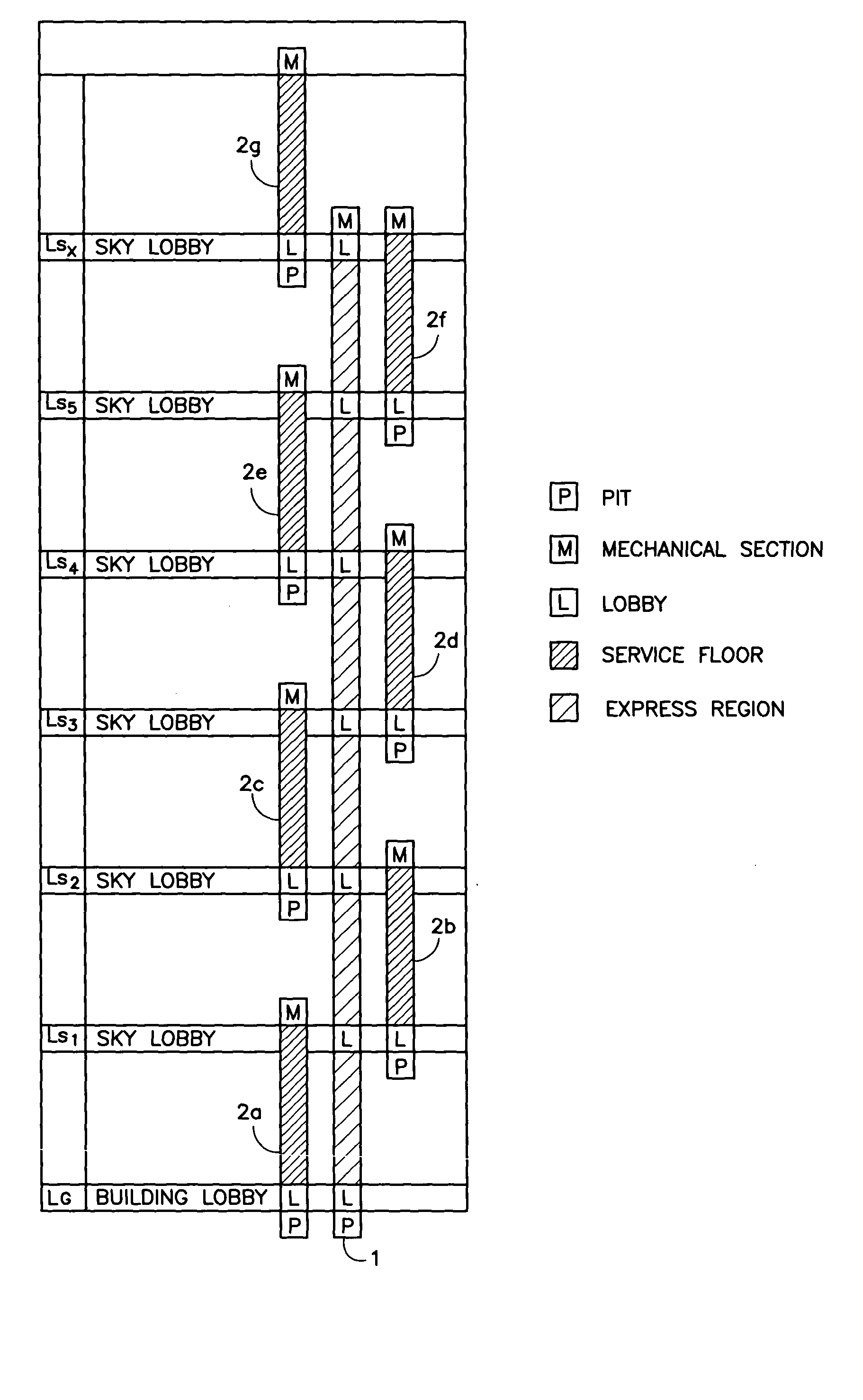
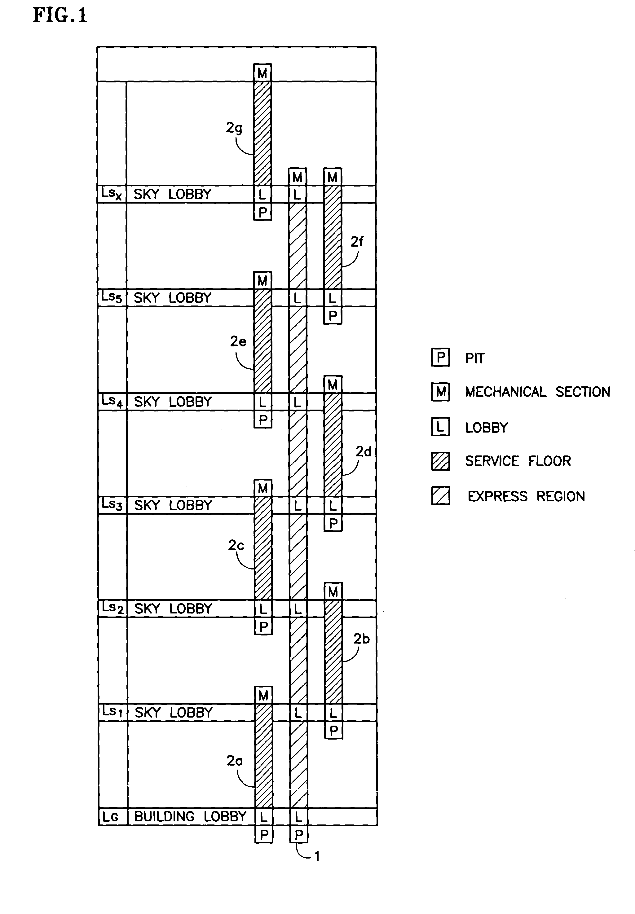
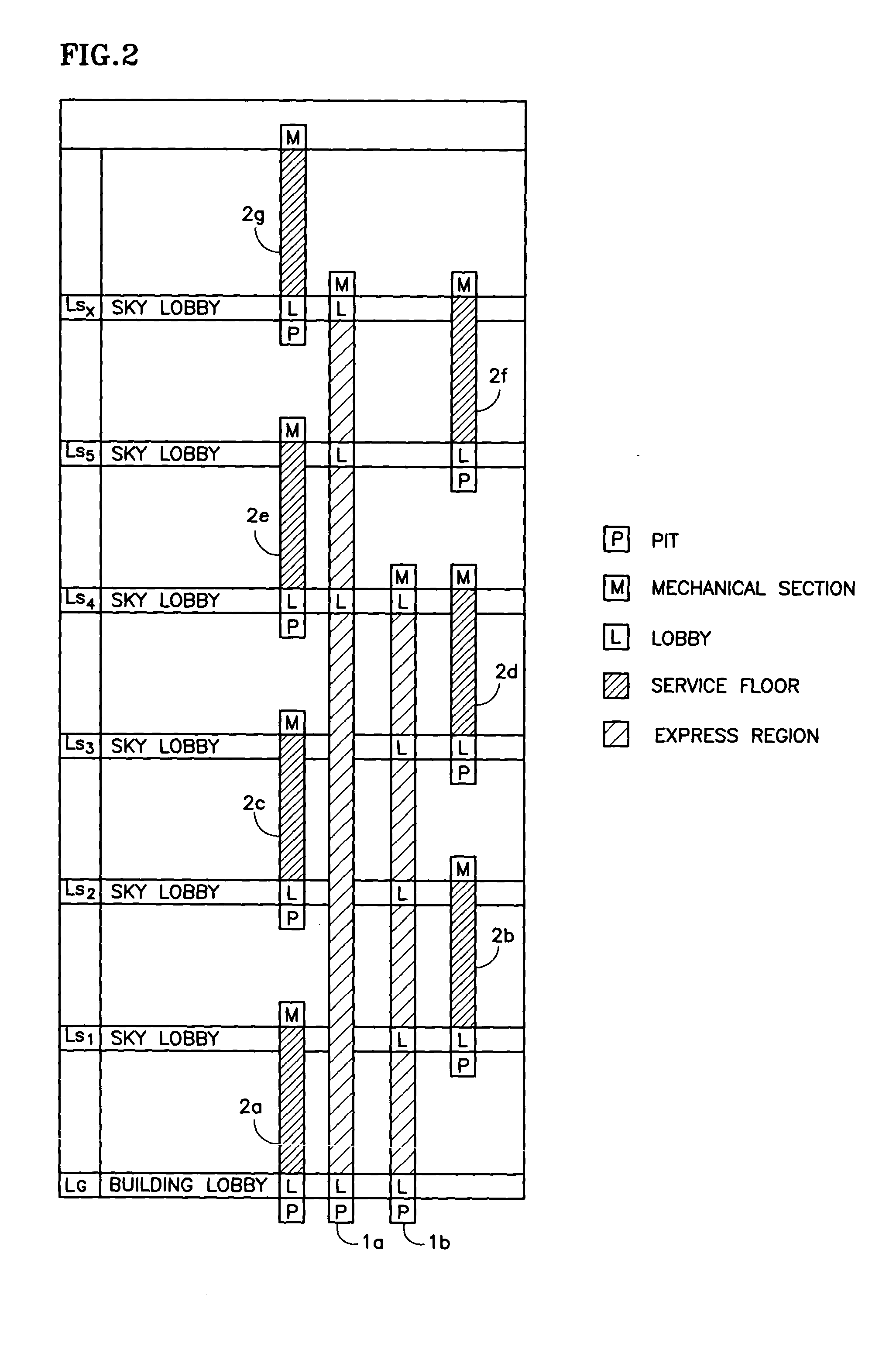
[0053] In the following, embodiments of the present invention will be explained with reference to the figures. In the constitution of the present invention, all of the connection floors and transfer floors in the elevator system of the conventional system (zone or sky lobby) are used as sky lobbies (a sky lobby for each bank of the local elevator), and a shuttle elevator is arranged to service the lobbies (sky lobbies) of the various banks of the local elevators (when there is a significant increase in the bank number, the shuttle elevators are zoned).

[0054] In FIG. 1, LG represents the building lobby at ground level. Sky lobbies Ls1-Lsx are arranged above said building lobby, with a prescribed number of floors between them. (1) represents a shuttle elevator that stops only at said building lobby LG and sky lobbies Ls1-Lsx, and the floors in the region between said lobbies are used the express region.

[0055] (2a) represents a local elevator that services various floors in the first...


PUM


Abstract

An elevator system is provided with multiple sky lobbies to reduce the space required for elevator shafts and the space required for the entire elevator system, as well as the required elevator speed and motor capacity.
Sky lobbies Ls1-Lsx are arranged above building lobby LG at ground level, with a prescribed number of floors between them. Shuttle elevator (1) stops only at building lobby LG and sky lobbies Ls1-Lsx, and passes through the various floors between lobbies by making them an express region. Local elevators service the floors in each bank between adjacent sky lobbies. Local elevators (2a), (2c), (2e), (2g) for the odd-numbered banks are arranged along the same elevator shaft, and local elevators (2b), (2d), (2f) for the even-numbered banks are arranged along another same elevator shaft.

Description

TECHNICAL FIELD OF THE INVENTION [0001] The present invention pertains to an elevator device that can move up and down along an elevator shaft of a building. More specifically, the present invention pertains to an elevator device of a multi-sky-lobby system in a high-rise building characterized by the fact that it has local elevators that stop at every floor and a shuttle elevator that moves in an express region and stops only at prescribed floors. BACKGROUND OF THE INVENTION [0002] Two types of elevators are used in high-rise buildings; those of the zone system and those of the sky lobby system. In the zone system, as shown in FIG. 8(a), the service floors are divided into plural banks by means of units A-E, and an express region is defined for operation between the building lobby LG (the lobby is on the ground floor) and the various banks except the lowermost bank. [0003] In FIG. 8, “P” stands for elevator pit; “M” stands for the mechanical section; and “L” stands for the lobby. T...

Claims


Application Information

Patent Timeline
IPC IPC(8): B66B1/16B66B1/20B66B9/00
CPCB66B9/00
Inventor URATA, MASAZUMI
Owner OTIS ELEVATOR CO
Why Eureka
Try Eureka