
Arrangement for merchandise display prongs

a technology for merchandise display and brackets, which is applied in the direction of show stands, show hangers, and display shelves, etc., can solve the problem of unsuitability for spring-preloaded feed devices

Inactive Publication Date: 2005-04-14
HL DISPLAY
View PDF9 Cites 11 Cited by
  • Summary
  • Abstract
  • Description
  • Claims
  • Application Information

AI Technical Summary

Benefits of technology

[0009] One object of the present invention is to provide an arrangement which allows the use of an easily mountable spiral spring roll for preloading a feed plate toward the attachment end of a merchandise prong without the spring roll interfering with the merchandise on the prong.
[0012] An arrangement of this type achieves inter alia the abovementioned aim of allowing very simple, cost-effective preloading of a feed device toward the attachment end of a merchandise prong without a spring roll forming part of the arrangement interfering with the merchandise on the prong. It is preferred that the spring is unrolled from the upper or lower part of the spring roll and that, after being diverted, it extends toward the attachment end of the arm on the opposite side of the roll. This allows very simple construction.
[0013] Furthermore, the spring roll is suitably arranged loosely in its seat and it is held in place under the action of the spring force. This makes possible very simple mounting and simple exchange of the spring, if required.

Problems solved by technology

In some cases, it is unsuitable to use spring-preloaded feed devices, in which case the feed device can instead be provided with a grip part, by means of which the feed device can be displaced forward along the prong for manual feed of the merchandise.

Method used


Image

  • Arrangement for merchandise display prongs
  • Arrangement for merchandise display prongs
  • Arrangement for merchandise display prongs

Examples


Embodiment Construction

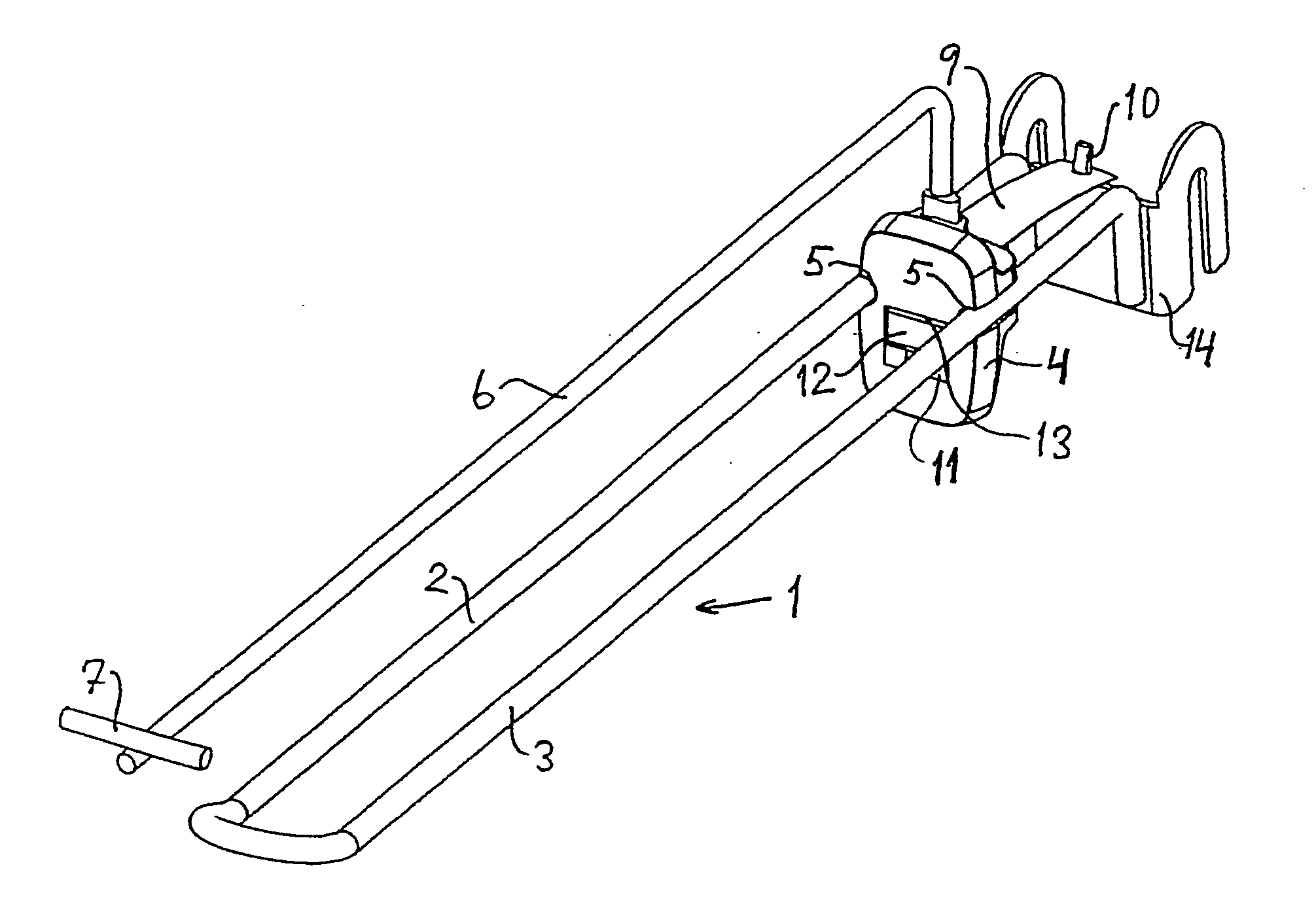
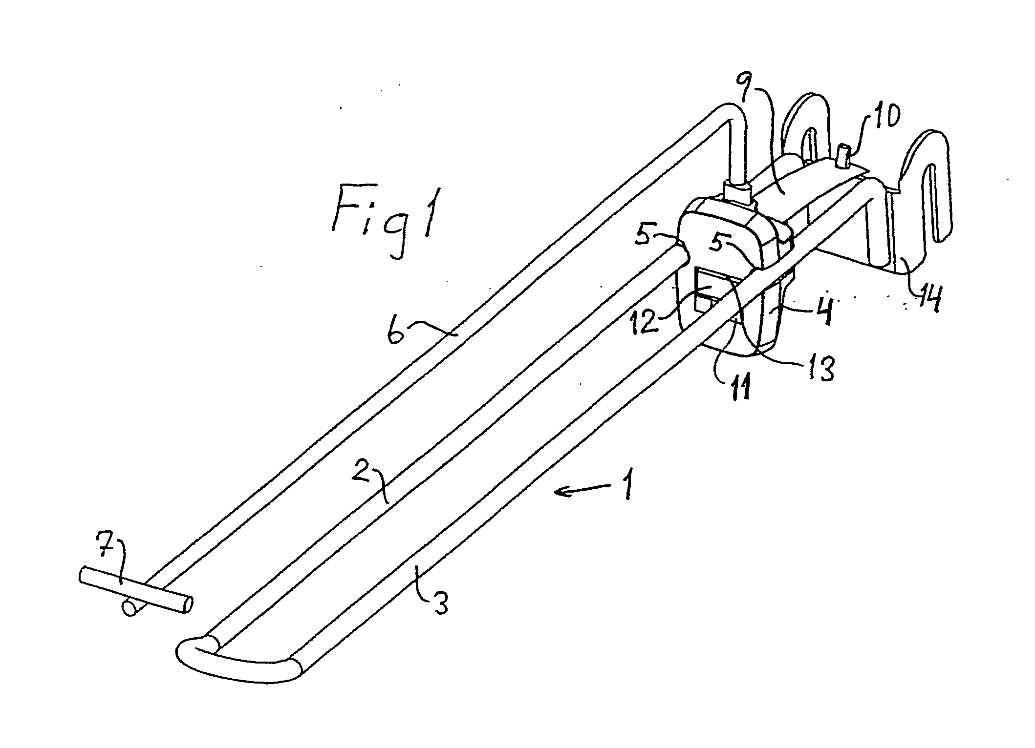
[0022] In FIG. 1, reference number 1 designates a merchandise display prong consisting of two wires 2, 3 which are joined at the outer end of the prong to form a U-shaped merchandise prong. The rear ends of the wires are connected to a mounting element 14 for mounting on a supporting structure, for example in the form of a perforated panel or upright.

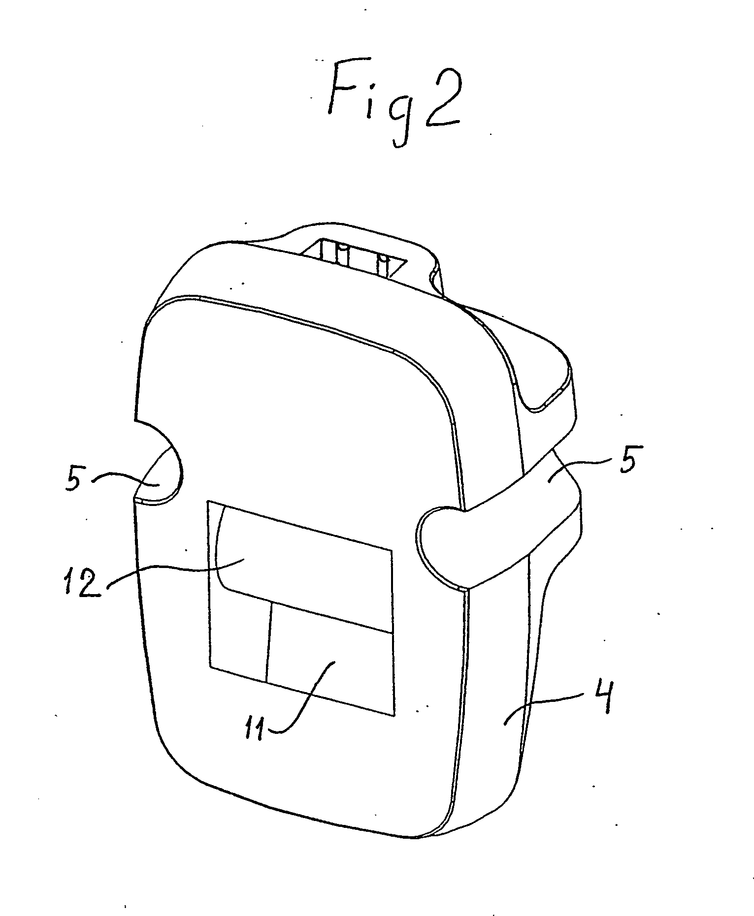
[0023] A feed device in the form of a slide 4 is fitted in between the wires. Opposite side edges of the slide 4 are made with guide grooves 5 (see also FIGS. 2 and 3) which interact with the wires 2, 3. Fastened in the top surface of the slide 4 is a feed arm 6 which, at its front end, is provided with a mounting means 7 for a label holder (not shown) which is intended to receive a label with information relating to the merchandise to be carried by the prong 1. By means of the arm 6 and the mounting means 7, the slide 4 can easily be pulled manually toward the front end of the prong 1 for feeding merchandise on the prong 1. In this co...


PUM


Abstract

Arrangement for merchandise display prongs intended for displaying merchandise in shops and the like, comprising a cantilever arm (1) for carrying the merchandise and a feed device (4) which is displaceable along the arm and provided with a grip part (6). The feed device is intended to be maneuvered manually in order to displace the merchandise carried by the arm (1) in the forward direction toward its free end for the purpose of bringing about a favorable display of the merchandise. The feed device (4) is spring-preloaded toward the attachment end of the cantilever arm. The arrangement comprises an unrollable spiral spring (9), the spring roll (8) of which is arranged in a seat on that side of the feed device (4) which faces the attachment end of the arm (1). The spring (9) is adapted so as to be unrolled from the spring roll (8) in the direction toward the free end of the arm and to be diverted around a diverting means (12) located in front of the roll in order to allow attachment of the outer end of the spring to the attachment end of the arm (1).

Description

FIELD OF THE INVENTION [0001] The present invention relates to an arrangement for merchandise display prongs intended for displaying merchandise in shops and the like, comprising a cantilever arm for carrying the merchandise and a feed device which is displaceable along the arm and provided with a grip part and which is intended, when acted on manually, to displace the merchandise carried by the arm in the forward direction toward its free end for the purpose of bringing about a favorable display of the merchandise, and which feed device is spring-preloaded toward the attachment end of the cantilever arm. BACKGROUND OF THE INVENTION [0002] There are a large number of merchandise display prongs on the market which are provided with feed devices which are spring-preloaded toward the free end of the prong. The reason for this is that the frontmost item of the merchandise carried by a prong is always to be located as far forward on the prong as possible, even if there are only a few ite...

Claims


Application Information

Patent Timeline
IPC IPC(8): A47F5/08
CPCA47F5/0823A47F1/128
Inventor AHLUND, BENGTSJOBERG, MARTEN
Owner HL DISPLAY
Learn More