
Flotation device for small airplanes

a technology for flying and small airplanes, applied in the direction of aircraft indicators, life-saving, vessel safety, etc., can solve the problems of difficult if not impossible to find the plan

Inactive Publication Date: 2005-04-14
SIMARD MARTIN
View PDF10 Cites 28 Cited by
  • Summary
  • Abstract
  • Description
  • Claims
  • Application Information

AI Technical Summary

Problems solved by technology

There have been too many situations where passengers and crew have survived the crash but died drowning or through exposure.
Once a small plane sinks, it is very difficult if not impossible to find the plane within the short span of time needed to save lives.

Method used


Image

  • Flotation device for small airplanes
  • Flotation device for small airplanes
  • Flotation device for small airplanes

Examples


Embodiment Construction

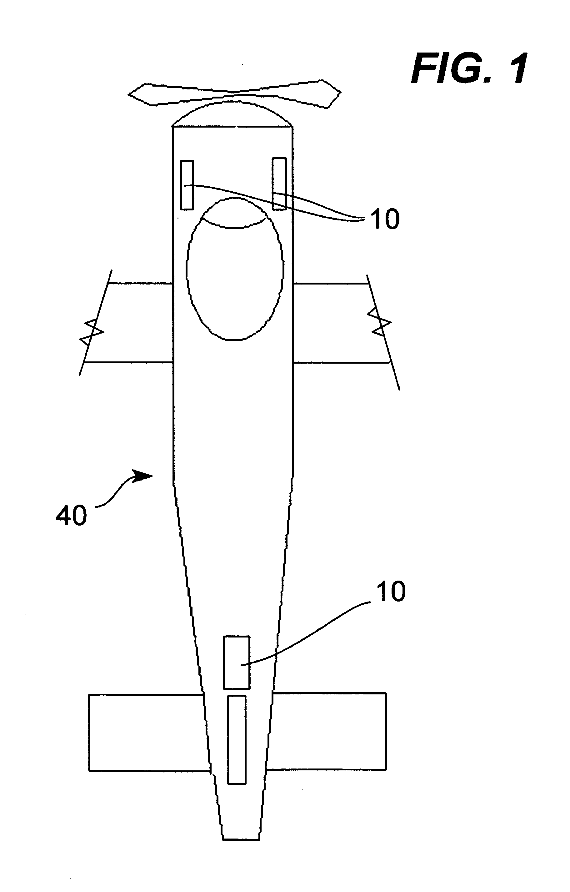
[0018]FIG. 1 Top view of a plane indicating the positions of the flotation devices.

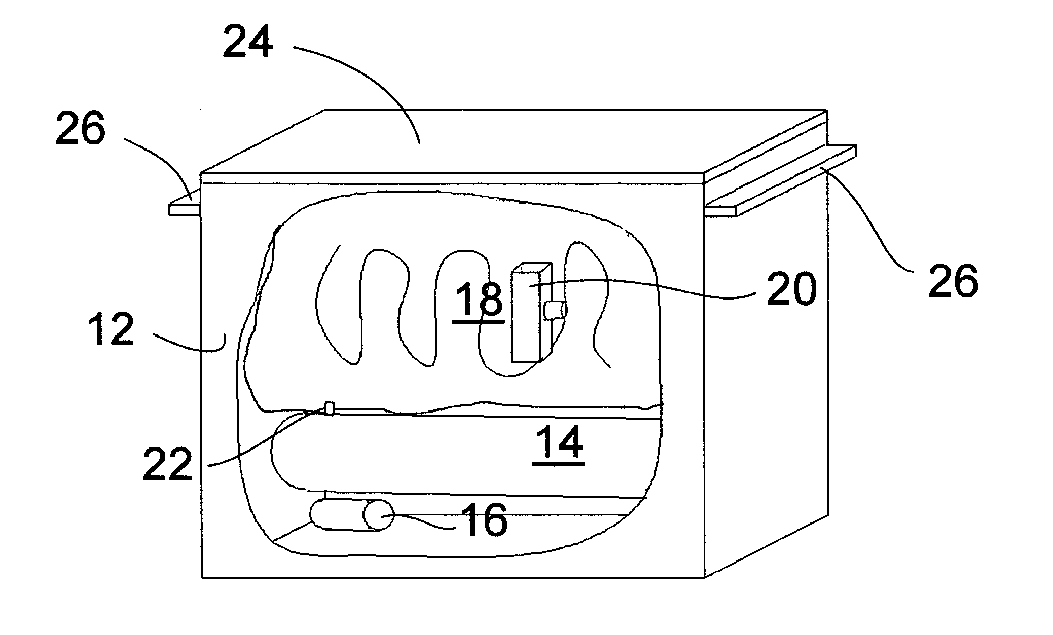
[0019]FIG. 2 Perspective view of a flotation device.

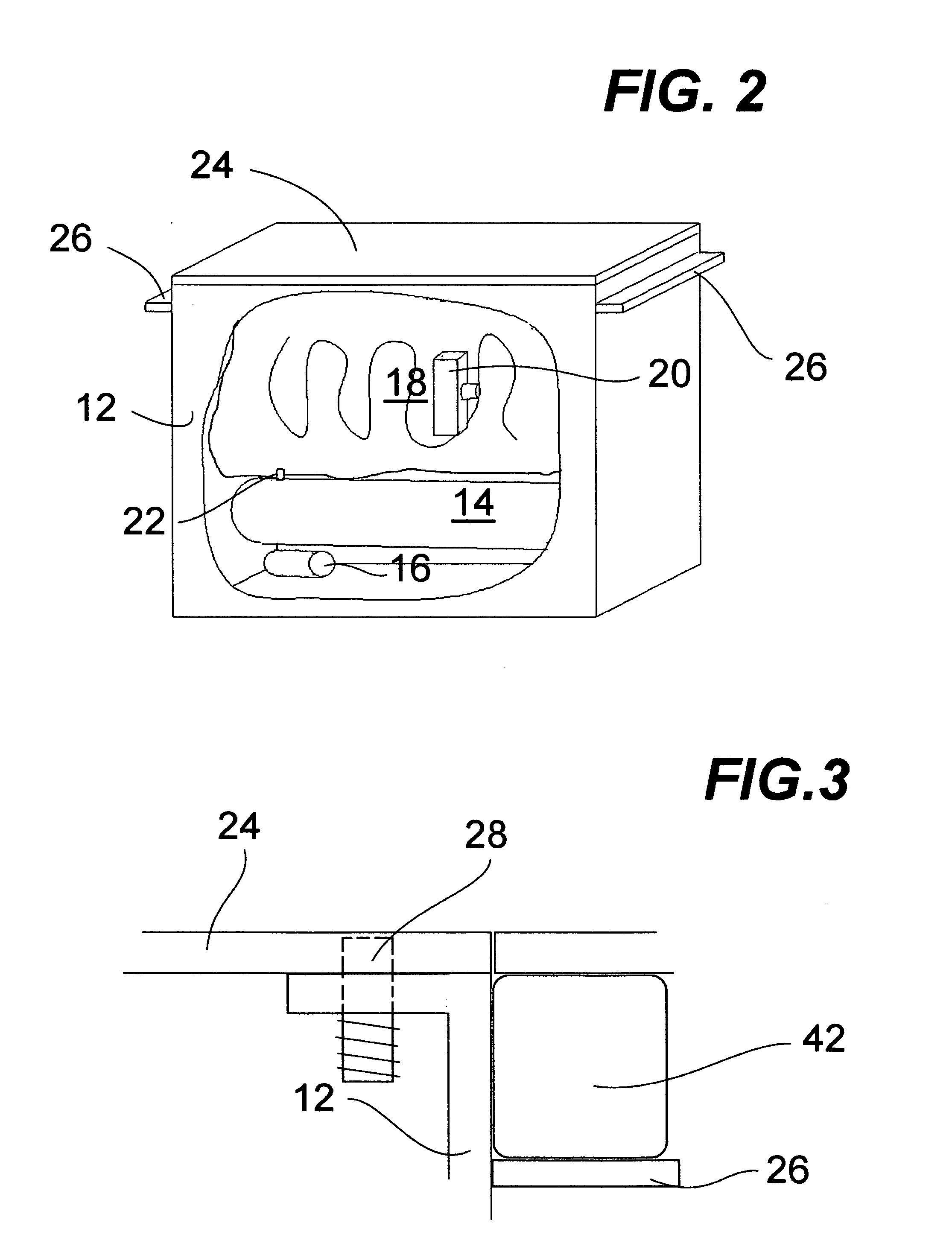
[0020]FIG. 3 Side view of the release system for the hatch.

[0021]FIG. 4 Bottom view of the plane with the flotation devices deployed.

DETAILED DESCRIPTION OF THE PREFERRED EMBODIMENT

[0022] At least one but preferably a plurality of flotation devices for small airplanes (10) are installed on a plane (40) Each one has a box (12) comprising a tank of compressed air (14); a trigger means (16); and a bag (18) having a beacon (20) attached thereto. The trigger means (16) is a combination of a water detector and G-force detector sensitive to abrupt deceleration much like car air bag systems. A manual triggering system can be used as well, if for any reason the pilot wants extra cushioning just prior to impact or if for one reason or other the bags (18) are not released. When a plane has more than one such box (12), only one needs to contain the beacon (...


PUM


Abstract

An emergency flotation device for crashed small airplanes which can be retrofited on most small airplanes as well as come preinstalled on new small airplanes, is self contained in a small container; has several independent triggering means; and has a visual as well as an RF beacon system integrated within to call for rescue.

Description

[0001] This application claims priority based on provisional application 60 / 509,180 filed Oct. 8, 2003BACKGROUND OF THE INVENTION [0002] 1. Field of the Invention [0003] The invention relates generally to flotation devices but more particularly to an emergency system of deployable bags to help small planes float after an emergency landing on water. [0004] 2. Background of the Invention [0005] Bush pilots flying small aircrafts such as cessnas or beechcrafts often fly over wilderness areas with hundreds of lakes. It should come as no surprise that airplane crash landings in lakes occur every now and then. There have been too many situations where passengers and crew have survived the crash but died drowning or through exposure. Once a small plane sinks, it is very difficult if not impossible to find the plane within the short span of time needed to save lives. [0006] A number of inventions relating to flotation devices for airplanes exist, they often comprise a combination parachutes...

Claims


Application Information

Patent Timeline
Patent Type & Authority Applications(United States)
IPC IPC(8): B60R21/16B63C9/22B64C1/34B64C25/56B64D25/18B64D25/20G01S1/02
CPCB64D25/18
Inventor SIMARD, MARTIN
Owner SIMARD MARTIN
Learn More