Data input device power management including beacon state

a data input device and power management technology, applied in the direction of static indicating devices, photomechanical devices, instruments, etc., can solve the problems of increasing the demand for longer intervals between increasing the number of times of battery replacement or recharging, and being left idle for significant periods of time, so as to increase the battery life and increase the amount of electrical power

Inactive Publication Date: 2005-04-14
MICROSOFT TECH LICENSING LLC
View PDF99 Cites 34 Cited by
  • Summary
  • Abstract
  • Description
  • Claims
  • Application Information

AI Technical Summary

Benefits of technology

[0014] Particularly advantageous use may be made of the capacitive sensing and power management aspects of the invention together with each other, to substantially increase battery life in a wireless cursor control device (e.g., computer mouse or trackball device) or other user operated data input device, especially one including circuit components (e.g., an optical tracking system and RF transmitter) that draw relatively large amounts of electrical power.

Problems solved by technology

The components of such devices are becoming increasingly power hungry, and the demand for longer intervals between battery replacement or recharging has increased.
Such devices are often turned on for ready usability but left idle for significant periods of time.
Without effective power management, continuous operation of such wireless peripherals will rapidly deplete the limited battery power of the device, thus requiring frequent battery replacement or recharging.
Heretofore, limited use of optical tracking systems has been made in wireless cursor control devices, due to the relatively large power requirements of both the optical tracking system and the wireless data transmitter.

Method used


Image

  • Data input device power management including beacon state
  • Data input device power management including beacon state
  • Data input device power management including beacon state

Examples


Embodiment Construction

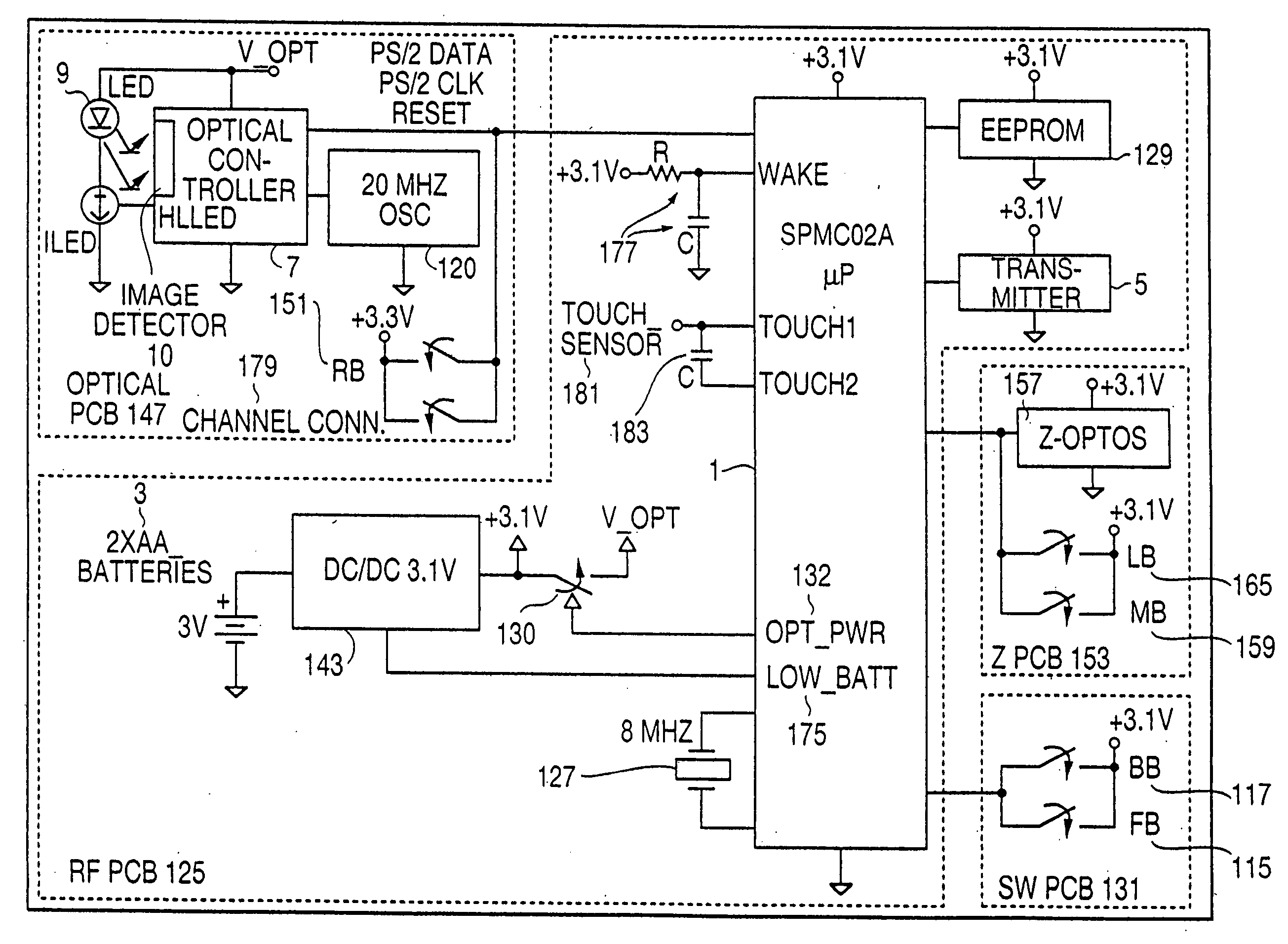
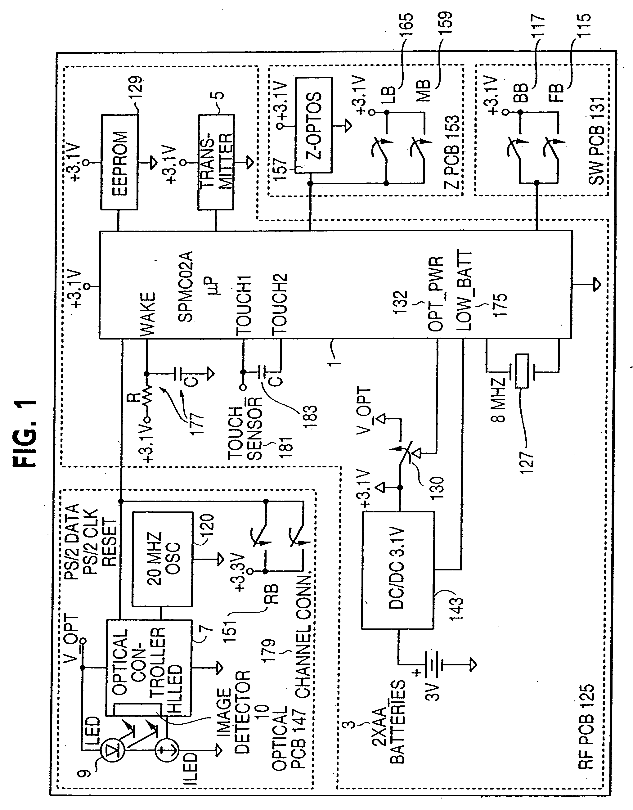
[0037] The present inventive systems and methods are described herein in terms of an exemplary application thereof within a computer input device, particularly a wireless, optically tracking computer mouse. It will be understood, however, that the inventions have much wider-ranging potential application. The capacitive sensing aspects of the present invention are not limited to power management, but rather can be implemented in virtually any device (data input device or otherwise) where it is desired to determine the presence or non-presence of an object or body portion in contact with or close proximity to another object. This includes many applications where various other types of proximity sensors have been used, e.g., water valve actuation in toilets, faucets and drinking fountains, automatic door control systems, alarm systems, security lock systems and safety interlock systems (e.g., for industrial equipment), etc.

[0038] It will be understood that the phrase “contact with or ...


PUM

PropertyMeasurementUnit
timeaaaaaaaaaa
timeaaaaaaaaaa
timeaaaaaaaaaa

Abstract

Power management is provided in a user operated data input device utilizing proximity sensing and switching between three or more power states. Switching between the power states occurs based upon the presence or absence of input activity, and an operation instrumentality (e.g., a hand) in close proximity to or contact with the device. Capacitive proximity sensing is carried out be detecting a relative change in the capacitance of a “scoop” capacitor formed by a conductor and a surrounding ground plane. In an optical surface tracking cursor control device embodiment, switching to and from a BEACON state, which provides a reduced flash rate of a surface illuminating light source, is carried out based upon a detected presence or absence of a trackable surface.

Description

[0001] This application is a continuation of U.S. application Ser. No. 09 / 991,651, filed Nov. 26, 2001, which is a divisional of U.S. application Ser. No. 09 / 948,099 filed Sep. 7, 2001, now U.S. Pat. No. 6,661,410.FIELD OF THE INVENTION [0002] The present invention relates to power management systems and methods that may be advantageously used in managing power consumption in electronic devices, particularly hand operated data input devices. The invention further concerns sensing systems and methods usable as part of a power management system, and for other purposes. More specifically, the invention relates to sensing and power management systems and methods that may be used to conserve battery power in wireless data input devices having components that consume power at a relatively high rate. BACKGROUND OF THE INVENTION [0003] Power management in electronic devices is becoming increasingly important as greater reliance is placed on battery power, e.g., for portable computers, perso...

Claims


Application Information

Patent Timeline
Patent Type & Authority Applications(United States)
IPC IPC(8): G06F3/038G03F7/004G03F7/038G06F1/32G06F3/03G06F3/0354G06F3/042H01H36/00
CPCG06F1/3203G06F1/3231G06F1/3259Y02B60/148Y02B60/1253Y02B60/1289G06F3/0317Y02D10/00G06F1/3271
Inventor CASEBOLT, MARK W.RENSBERGER, GARYGORMAN, SEAN
Owner MICROSOFT TECH LICENSING LLC
Why Eureka
Try Eureka