
Method and system for using an optical sensor array to control a labeling device

a technology of optical sensor array and labeling device, which is applied in the direction of program control, recording head arrangement, record information storage, etc., can solve the problems of limited labeling of discs by most consumers, specialized and expensive equipment is required to professionally label optical discs, and limited direct writing methods

Inactive Publication Date: 2005-04-14
HEWLETT PACKARD DEV CO LP
View PDF13 Cites 16 Cited by
  • Summary
  • Abstract
  • Description
  • Claims
  • Application Information

AI Technical Summary

Benefits of technology

The patent describes a method for using an optical sensor to control a labeling device. The sensor scans the surface of a material and collects data about its texture. This data is then used to control the labeling device. The technical effect is that this method allows for precise and automated labeling of materials based on their surface texture.

Problems solved by technology

However, very specialized and expensive equipment is required to professionally label an optical disc.
Consequently, the labeling of discs by most consumers is typically limited to either printing on separate adhesive labels that are subsequently adhered to the non-data side of the disc, handwriting with a marker directly on the disc, or handwriting on an adhesive label.
This direct writing method, however, is limited by the resolution of the optical disc drive to track the position of the laser with respect to the non-data surface of the disc as well as the need for motor speed control.

Method used


Image

  • Method and system for using an optical sensor array to control a labeling device
  • Method and system for using an optical sensor array to control a labeling device
  • Method and system for using an optical sensor array to control a labeling device

Examples


Embodiment Construction

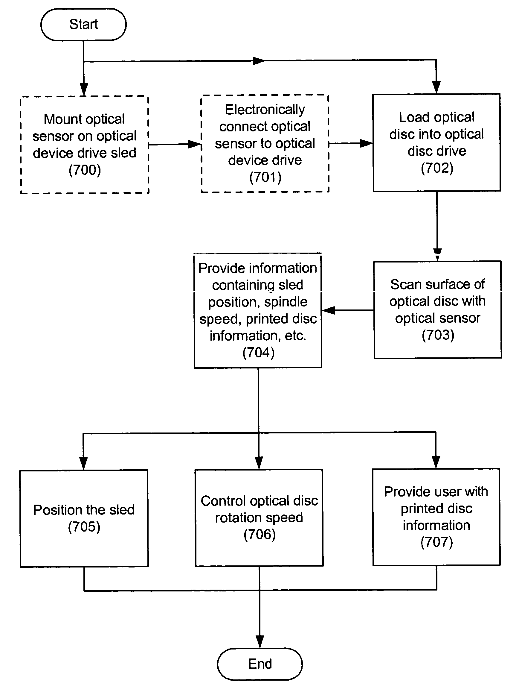
[0020] The present specification describes a method and a system for controlling an optical disc drive based on information received from an optical sensor array. The optical sensor array may provide information including, but in no way limited to, the position of an optical disc drive moveable member, rotational speed of an optical disc, and / or information regarding previously printed disc information.

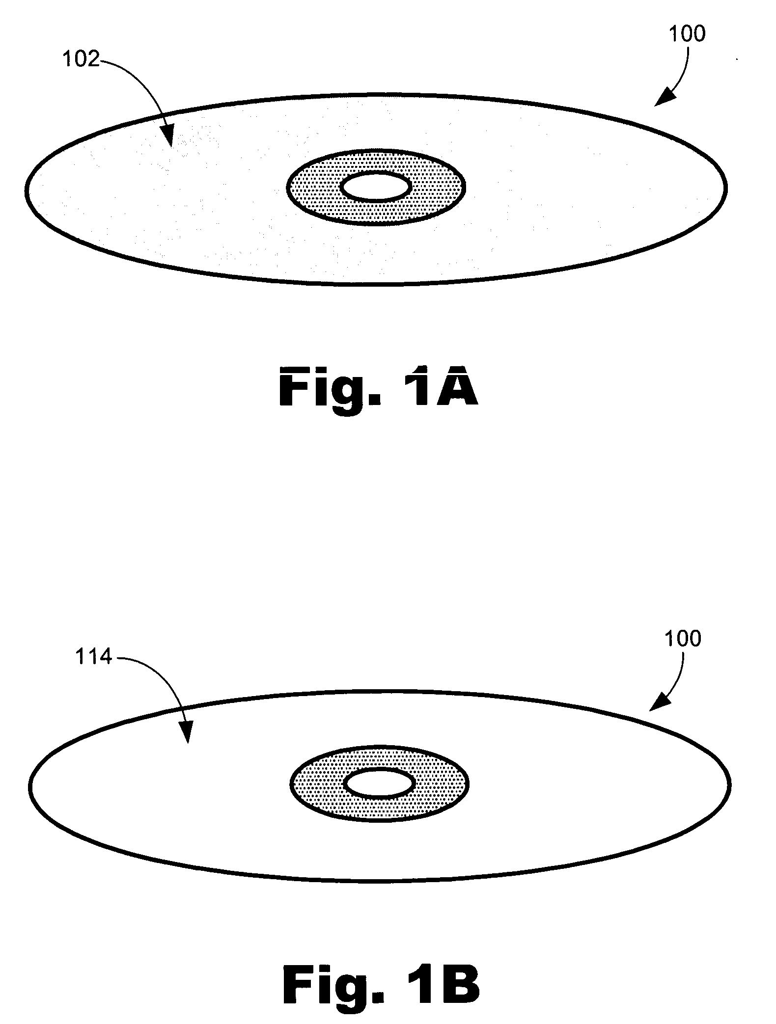
[0021] As used in this specification and in the appended claims, the term “optical disk” is meant to be understood as any data storage disk capable of containing optically readable information including, but in no way limited to, compact discs (CDs), Digital Video (or Versatile) Discs (DVDs), or game system discs in a variety of formats. Additionally, an angle of incidence is meant to be understood as an angle between an incident ray of light and the perpendicular to a surface. Moreover, the term “imageable medium” is meant to be understood as any material whose lucidity may be selec...


PUM

PropertyMeasurementUnit
surface textureaaaaaaaaaa
surfaceaaaaaaaaaa
rotational speedaaaaaaaaaa

Abstract

A method for using an optical sensor array to control a labeling device includes scanning a surface texture of an imageable media with the optical sensor array, collecting surface data corresponding to the surface texture of the imageable media, and controlling the labeling device in response to the surface data.

Description

BACKGROUND [0001] Optical discs have fast become an industry standard for data storage in the fields of computers video and music Optical discs include, but are not limited to, compact discs (CDs), Digital Video (or Versatile) Discs (DVDs), and game system discs in a variety of formats. Commercially produced optical discs usually have digital data recorded on one side of the disc and a visual display printed on the opposite side of the disc. [0002] In some instances, optical discs are created that can store data on both sides of the disc. However, in most cases, it is desirable to limit the optical disc data to a single side of the disc, leaving the other side of the disc for printed text, patterns, or graphics. The printed labeling on a non-data side of an optical disc can include a decorative design, text identifying the data stored on the disc, or both. [0003] As optical technology has advanced, writeable and rewritable optical discs as well as equipment for writing onto the disc...

Claims


Application Information

Patent Timeline
Patent Type & Authority Applications(United States)
IPC IPC(8): B41J3/407B41J11/00G11B7/0037G11B7/0045G11B7/09B65C9/26G11B23/40
CPCB41J3/4071G11B23/40G11B7/0037B41J11/009B65C9/26
Inventor KOLL, ANDREWANDERSON, DARYL E.VAN BROCKLIN, ANDREW L.
Owner HEWLETT PACKARD DEV CO LP
Learn More