Operation system

a technology of operation room and cord, applied in the field of operation system, can solve the problems of cord occupying the floor of the operation room, specific medical devices cannot be controlled, and the cord becomes a problem,

Active Publication Date: 2005-04-14
OLYMPUS CORP
View PDF46 Cites 98 Cited by
  • Summary
  • Abstract
  • Description
  • Claims
  • Application Information

AI Technical Summary

Benefits of technology

[0013] In an operation system according to the present invention, a radio foot switch is turned on, a pedal is pressed, and a medical device as a control target is turned on. Then, a signal outputted by pressing the pedal is transmitted together with an ID code. The medical device as the control target receives the transmitted signal, and stores the ID code so as to identify a remote control device. Further, the medical device returns the ID code and, thus, the radio foot switch stores the ID code so as to identify, as the medical device as the control target, the medical device which transmits the ID code. After that, upon pressing the pedal, an operating signal is transmitted to the ID code of the medical device as the control target and thus the remote control operation is possible without fail when the radio foot switch is not dedicated to the medical device as the control target.

Problems solved by technology

Therefore, when a plurality of medical devise are arranged to an operation room, the number of cords corresponding to the number of medical devices are wired on the floor and the cords become a problem because the user's foot is caught by the cord and the user must step over the cord.
However, the radio propagation has a specific problem that electric waves are propagated over the wide range and therefore only a specific medical device cannot be controlled.
According to a method for controlling only the specific medical device by providing a specific ID for the medical device and the foot switch, the foot switch in this case is dedicated for the corresponding medical device and, upon using a plurality of medical devices, a plurality of foot switches are still provided and the problem that the cords occupy the floor of the operation room is not solved.
Further, when one of the corresponding medical device and the corresponding foot switch is damaged, there is a problem of the maintenance that the two devices must be repaired because of the specific IDS of the two devices.
In addition, when the foot switch is not found, the medical device is not controlled with the same-functional foot switch having another ID.

Method used


Image

  • Operation system
  • Operation system
  • Operation system

Examples


first embodiment

[0031] (First Embodiment)

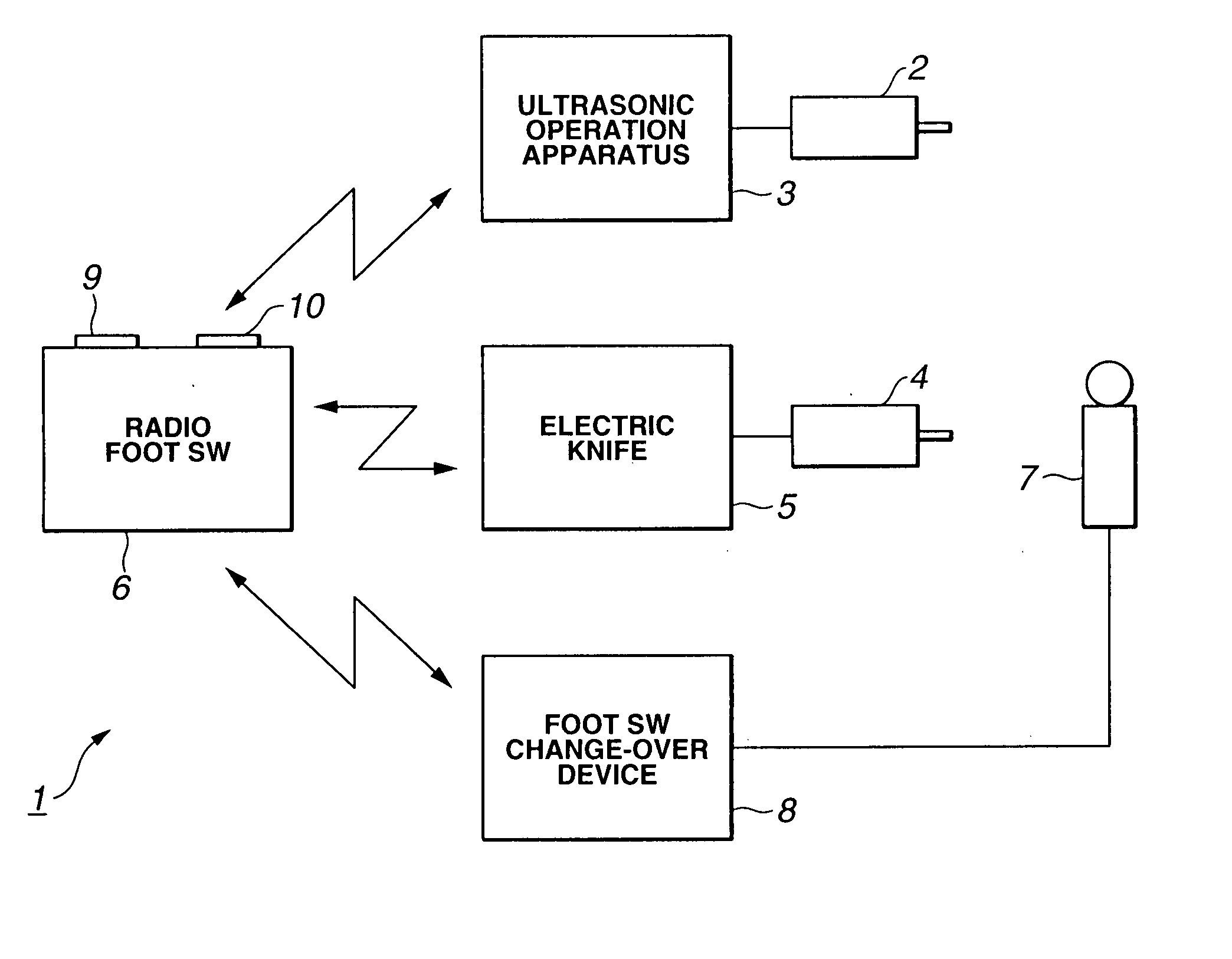
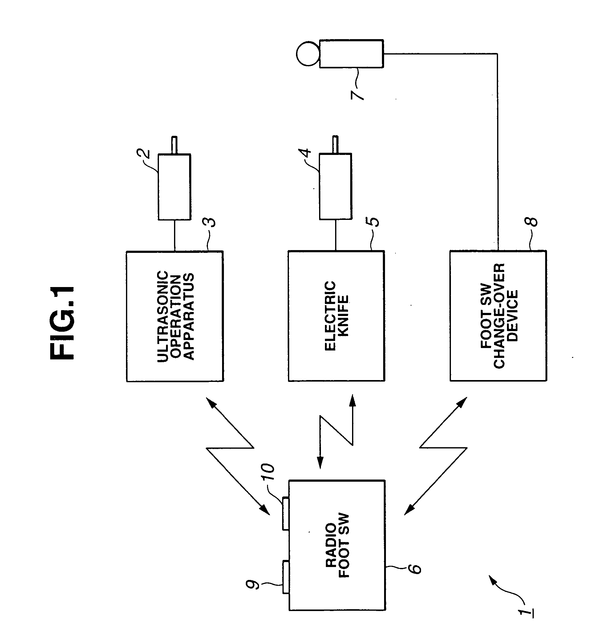
[0032] An electric operation system according to the first embodiment of the present invention comprises one radio foot switch and a plurality of medical devices. The operation for pressing the radio foot switch corresponds to the operation for turning on / off one medical device.

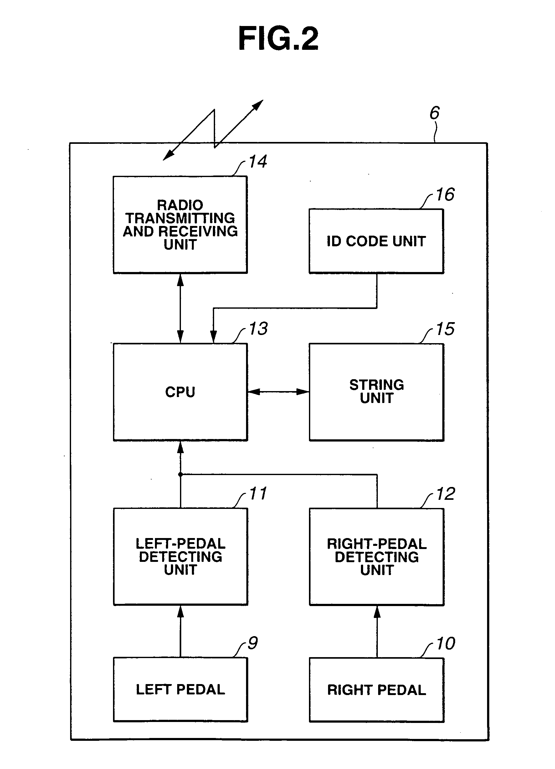
[0033] FIGS. 1 to 5 relate to the first embodiment of the present invention. FIG. 1 is a diagram showing the entire structure of the electric operation system according to the first embodiment of the present invention. FIG. 2 is a block diagram showing the schematic structure of a radio foot switch shown in FIG. 1. FIG. 3 is a block diagram showing the schematic structure of an ultrasonic operation apparatus shown in FIG. 1. FIG. 4 is a block diagram showing the schematic structure of a foot switch change-over device. FIG. 5 is a flowchart showing the control operation according to the first embodiment.

[0034] Referring to FIG. 1, the electric operation system 1 according to the firs...

second embodiment

[0083] (Second Embodiment)

[0084] The structure according to the second embodiment of the present invention is basically the same as that according to the first embodiment. However, the foot switch change-over device has voice selecting means or the like which sets the medical device corresponding to one radio foot switch.

[0085] Hereinbelow, a description is given of the second embodiment with reference to FIGS. 4 and 6.

[0086] As described with reference to FIG. 4, the microphone 7 is connected to the foot switch change-over device 8, and the microphone 7 can read voice information of the user such as the operator.

[0087] Further, the storing unit 34 registers necessary voice data. The storing unit 34 receives the voice information, and when it is determined that the received voice information corresponds to the registered voice data as compared with the registered voice data, the control operation is performed corresponding to the voice data.

[0088] When the operator inputs “the u...

third embodiment

[0110] (Third Embodiment)

[0111]FIG. 7 is a diagram showing the entire structure of an electric operation system according to a third embodiment of the present invention. FIG. 8 is an explanatory diagram showing the operation of the electric operation system according to the third embodiment of the present invention.

[0112] According to the third embodiment, unlike the electric operation system according to the first embodiment, only one foot switch is used and setting functions are concentrated in the medical device.

[0113] The radio foot switch 6 is turned on and then the corresponding foot switch shifts to an initial mode (#1) whereupon a self-recognizing code is continuously transmitted (#2).

[0114] Further, the medical device (e.g., ultrasonic operation apparatus 3) shifts to the initial mode after the turning-on operation (#101). In this case, the medical device which is controlled by the foot switch is not set and a plurality of turned-on medical devices can receive the ID cod...


PUM


Abstract

In an operation system according to the present invention, a radio foot switch is turned on and a pedal is pressed. Further, a medical device as a control target is turned on and a signal indicating the press operation of the pedal is transmitted together with an ID code. The medical device as the control target receives the signal and stores the ID code, thus to enter an identification state of a remote control device. The medical device returns the ID code and thus the radio foot switch stores the ID code so that the radio foot switch identifies, based on the returned ID code, the medical device which transmits the ID code as the control target. Then, upon pressing the pedal, an operating signal is transmitted to the ID code of the medical device as the control target and thus the remote control operation is possible without fail between the radio foot switch and the medical device as the control target which are not specified.

Description

CROSS-REFERENCE OF RELATED APPLICATION [0001] The present application is based on the priority of Japanese Patent Application No. 2002-290411 filed to Japan on October 2, 2002. The disclosure is referred to the description, claims, and drawings of the present invention. TECHNICAL FIELD [0002] The present invention relates to an operation system which performs the operation by using a medical device. BACKGROUND ART [0003] As one conventional art, Japanese Unexamined Patent Application Publication No. 2000-287989 discloses an ultrasonic operation apparatus which uses a method for controlling an ultrasonic output by switching on / off a foot switch connected by wiring. [0004] Further, Japanese Unexamined Patent Application Publication No. 11-318935 discloses a wiring foot switch integrally comprising a plurality of switches for controlling a plurality of medical devices, which uses a method for controlling the medical devices by detecting the user's foot position, by displaying the medic...

Claims


Application Information

Patent Timeline
Patent Type & Authority Applications(United States)
IPC IPC(8): A61B17/00A61B17/32A61B19/00
CPCA61B17/00A61B17/320068A61B2019/448A61B2017/00973A61B2017/00017A61B90/98A61B2017/320082Y10S128/903
Inventor TAKAHASHI, HIROYUKI
Owner OLYMPUS CORP
Why Eureka
Try Eureka