Method and device for applying a label to a packet

Inactive Publication Date: 2005-04-21
GD SPA
View PDF8 Cites 7 Cited by
  • Summary
  • Abstract
  • Description
  • Claims
  • Application Information

AI Technical Summary

Benefits of technology

[0007] It is an object of the present invention to provide a method and device for applying labels to packets,

Problems solved by technology

Controlling the movements of the pickup head and packets, however, is extremely difficult, especially when the precision required is considerable.
Known

Method used


Image

  • Method and device for applying a label to a packet
  • Method and device for applying a label to a packet
  • Method and device for applying a label to a packet

Examples


Example

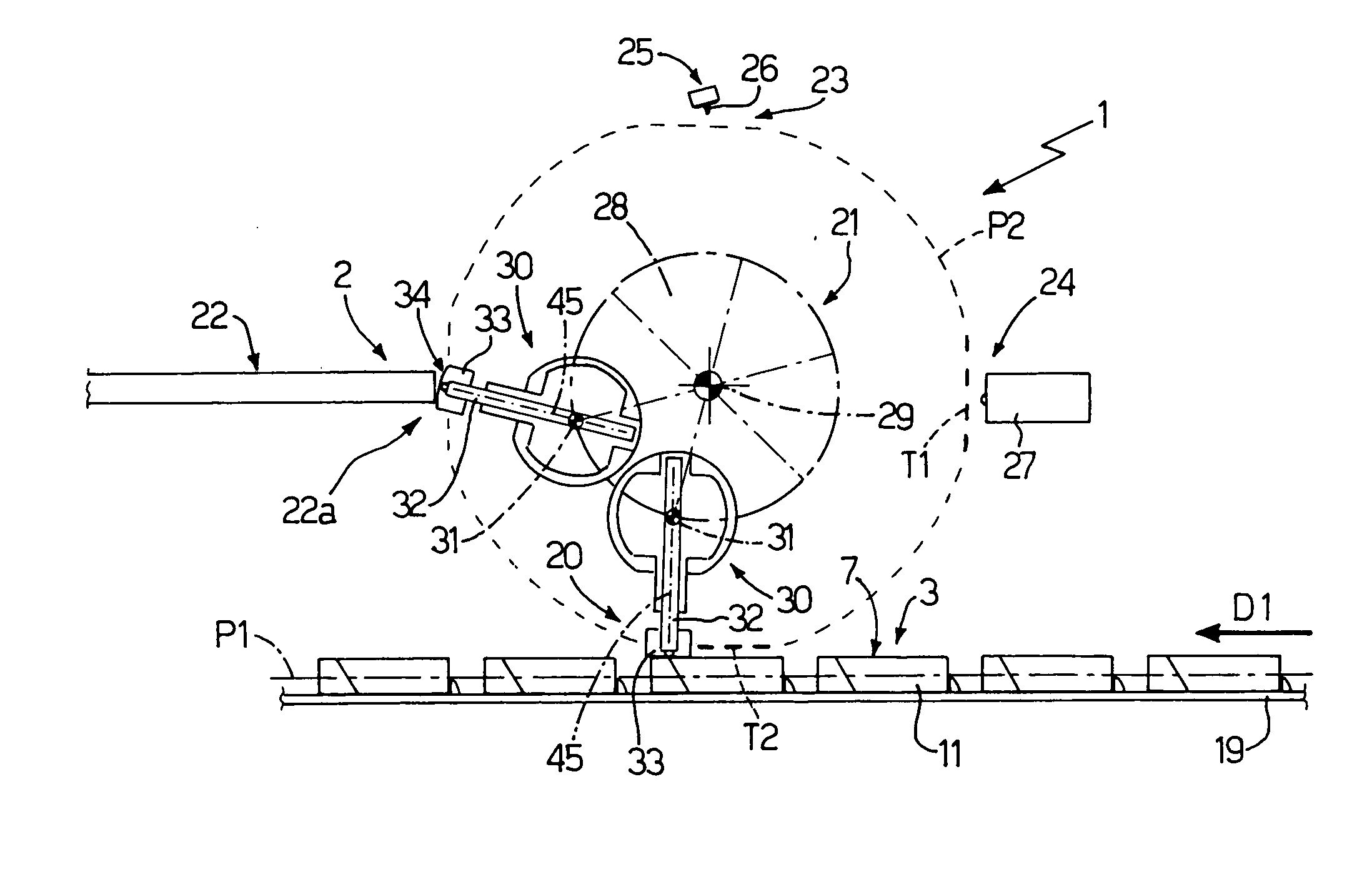
[0015] Number 1 in FIG. 1 indicates as a whole a device for applying a label 2 to a packet 3 of cigarettes fed continuously along a conveying path P1 extending in a substantially horizontal direction D1 parallel to the FIG. 1 plane.

[0016] With reference to FIG. 14, packet 3 is a rigid, hinged-lid type, comprises a cup-shaped body 4 and a lid 5, and has, once it is applied, a label 2 located partly on lid 5 and partly on cup-shaped body 4. When lid 5 is in the closed position, packet 3 comprises a front face 6, a rear face 7, a bottom face 8, a top face 9, and two lateral faces 10 and 11. Lid 5 and the cup-shaped body are hinged along rear face 7, and are separated by a parting line 12 along front face 6, and by two parting lines 13 along respective lateral faces 10 and 11 label 2 comprises a central portion 14 which adheres to rear ace 7; and a lateral portion 15 which adheres to lateral face 10 and is divided into two portions 16 and 17 by a tear line 18 located at parting line 13...


PUM

PropertyMeasurementUnit
Angleaaaaaaaaaa

Abstract

A method and device for applying a label to a packet of cigarettes travelling in a given direction along a conveying path; to apply the label to the packet, a pickup head is fed along a feed path by rotating the pickup head about two axes parallel to each other, and by moving the pickup head radially with respect to one of the two axes.

Description

[0001] The present invention relates to a method and device for applying a label to a packet. [0002] The present invention may be used to advantages for packets of cigarettes, to which the following description refers purely by way of example. BACKGROUND OF THE INVENTION [0003] Known methods of applying labels to packets of cigarettes comprise feeding the packets of cigarettes along a conveying path and through a labelling station; withdrawing a label from a store by means of a pickup head; feeding the pickup head along a feed path through the labelling station; and applying the label to a respective packet of cigarettes at the labelling station. [0004] Known methods should be capable of conveying each packet and the pickup head applying the label to the packet in such a manner as to prevent relative slide between the packet and label, and ensure a high degree of precision in applying the label. Controlling the movements of the pickup head and packets, however, is extremely difficul...

Claims


Application Information

Patent Timeline
IPC IPC(8): B65C9/12B65C1/02B65C1/04B65C9/00B65C9/14B65C9/20B65C9/36B65C9/40
CPCB65C1/023B65C1/04B65C9/0015B65C9/14B65C9/20Y10T156/1771B65H2406/345Y10T156/1749Y10T156/1744Y10T156/178Y10T156/1768B65H2301/33216
Inventor SPATAFORA, MARIOTALE', FABRIZIOPOLAZZI, ALBERTO
Owner GD SPA
Why Eureka
Try Eureka