First flush rainwater diverter and collection system

a rainwater diverter and collection system technology, applied in water cleaning, sedimentation settling tanks, artificial water canals, etc., can solve problems such as water was

Active Publication Date: 2005-04-21
WADE RODNEY GEORGE
View PDF12 Cites 12 Cited by
  • Summary
  • Abstract
  • Description
  • Claims
  • Application Information

AI Technical Summary

Problems solved by technology

This can result in

Method used


Image

  • First flush rainwater diverter and collection system
  • First flush rainwater diverter and collection system

Examples


Embodiment Construction

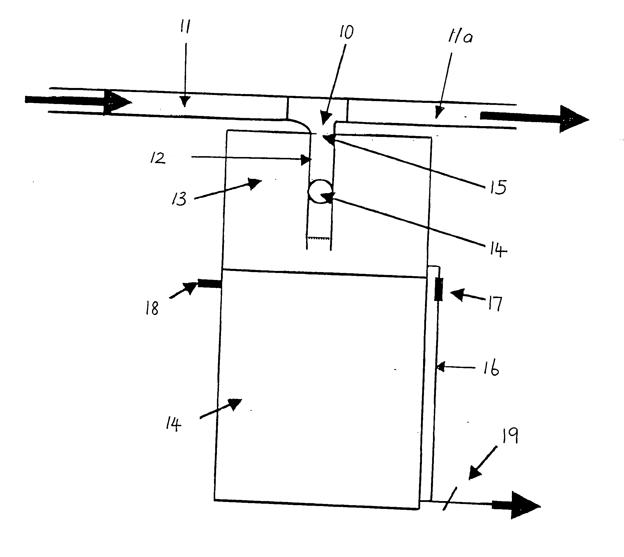
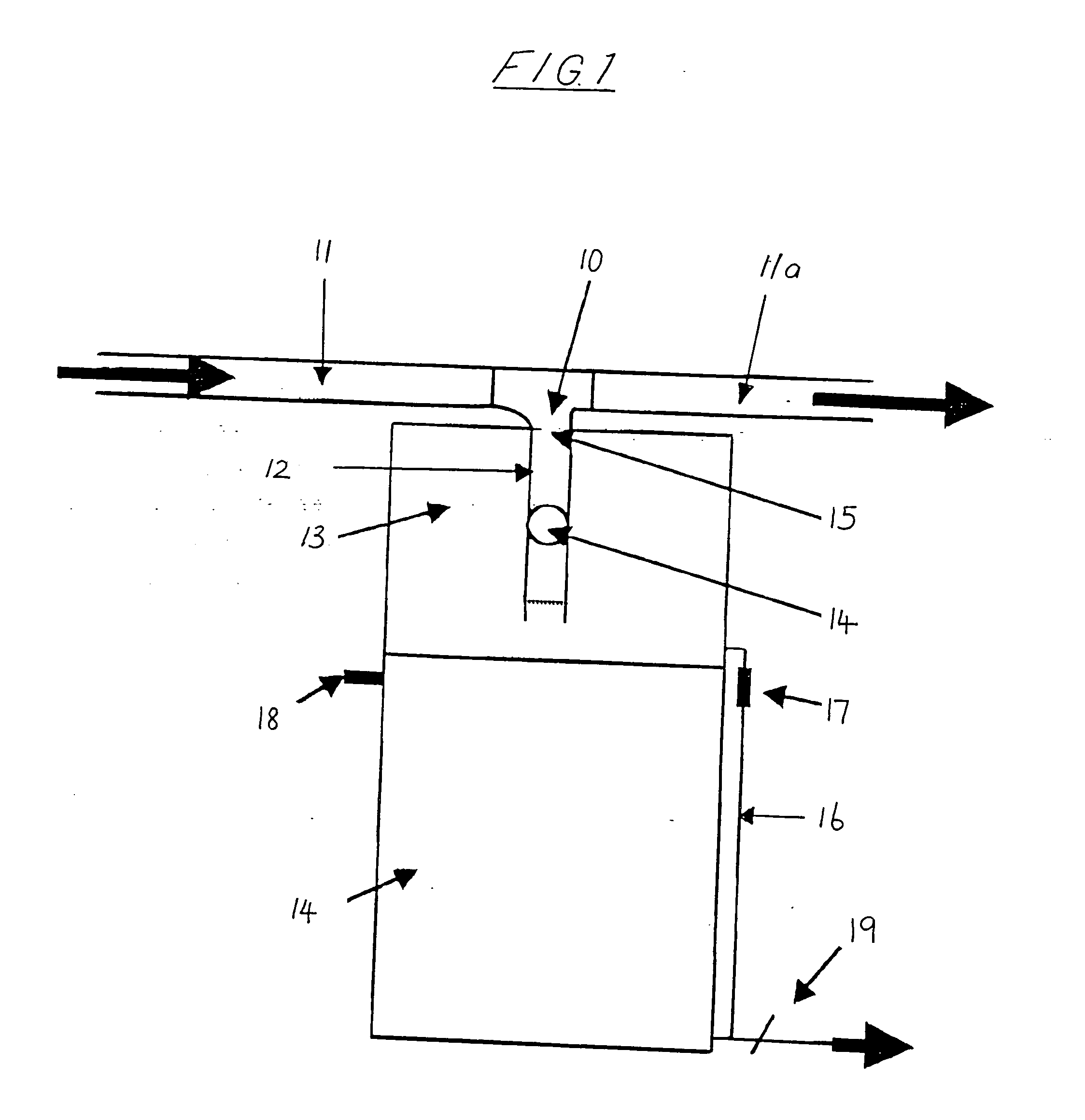
[0007] The effective volume of the primary chamber is related to the size of the rainwater catchment area and the degree of contamination so that diversion and storage of essentially only the contaminated portion of the rainwater results. An Industry Development Standard requires the collection of 0.5 mm over the catchment area where light contamination occurs and up to approximately 2.0 mm where heavy contamination occurs such-as from roofs with fruit bat droppings.

[0008] The “effective volume” of the primary chamber is the volume to which the rainwater can rise before the float seals off the admission of further rainwater. The effective volume can be adjusted by altering the float.

[0009] For instance when the float comprises a ball, adjustment can be readily achieved by adding one or more additional balls to the fall pipe. Each ball added will lower the cut-off level of the rainwater in the primary chamber and thereby reduce the volume of rainwater necessary to seal the primary ...


PUM

PropertyMeasurementUnit
Lengthaaaaaaaaaa
Lengthaaaaaaaaaa
Flow rateaaaaaaaaaa

Abstract

A first flush rainwater diverter and collection system for use with rainwater storage tanks primarily in domestic situations. The system comprises primary (13) and secondary (14) storage chambers, a T-piece (10) for connection in a rainwater flow path, a fall pipe (12) connected to the T-piece and extending into the primary storage chamber, a float within the fall pipe which seals on a seat when the level of rainwater reaches a preset level, a rainwater flow regulator (17) which regulates the flow of rainwater from the primary storage chamber to the secondary storage chamber, an overflow (18) and an outlet (19) in the secondary storage chamber.

Description

BACKGROUND OF THE INVENTION [0001] This invention relates to a first flush rainwater diverter and collection system, that is, a system for separating and storing an initial flow of normally contaminated rainwater flowing from a catchment region, such as the roof of a building, to a storage region, such as a large capacity tank. The invention is a further development of the invention described in Australian Patent No. 692835, the contents of which are incorporated herein by reference. [0002] In the aforementioned patent, there is disclosed a rainwater diverter comprising a T-piece with associated rainwater fall pipe. The T-piece is adapted for connection in the rainwater flow path to intercept the flow of rainwater flowing into a downpipe or directly to a storage or usage area. The fall pipe incorporates a ball-float which seals on a seat when the fall pipe is at least partly full of water, an outlet which limits the rate of flow from the fall pipe in comparison with the maximum flow...

Claims


Application Information

Patent Timeline
IPC IPC(8): B01D21/02
CPCB01D21/02B01D21/2405B01D21/2444B01D21/30B01D2221/02B01D2221/12B01D21/307B01D21/34Y10T137/2675
Inventor WADE, RODNEY GEORGE
Owner WADE RODNEY GEORGE
Why Eureka
Try Eureka