Bumper beam having face with supported angled wall

a technology of bumper beams and angled walls, which is applied in the direction of bumpers, vehicle components, vehicular safety arrangments, etc., can solve the problems of thick sections that are often required by the extension process and materials, and achieve the effect of predicting and achieving the desired energy absorption upon impa

Inactive Publication Date: 2005-04-21
SHAPE CORP
View PDF18 Cites 9 Cited by
  • Summary
  • Abstract
  • Description
  • Claims
  • Application Information

AI Technical Summary

Benefits of technology

[0005] In one aspect, a bumper beam for a passenger vehicle includes a cross section having an impact-receiving front wall, a rear wall, and parallel top and bottom walls combining to define an exterior tube. An inner reinforcement wall extends between the front and rear walls and subdivides the exterior tube into upper and lower tubular halves. The front wall includes a vertical section that extends parallel the rear wall and further includes an angled section connected by a bent section to the vertical section. The reinforcement wall extends parallel the top and bottom walls and is connected to and supports the angled section at a location spaced from the bent section. By this arrangement, the reinforcement wall combines with the vertical and angled sections of the front wall and with the other walls to provide predictable and desired energy absorption upon impact.

Problems solved by technology

However, extruding processes and materials often require thick sections to obtain the strengths required.

Method used


Image

  • Bumper beam having face with supported angled wall
  • Bumper beam having face with supported angled wall
  • Bumper beam having face with supported angled wall

Examples


Embodiment Construction

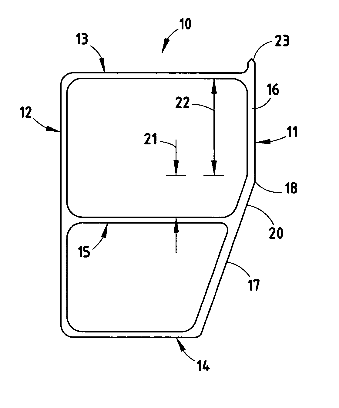
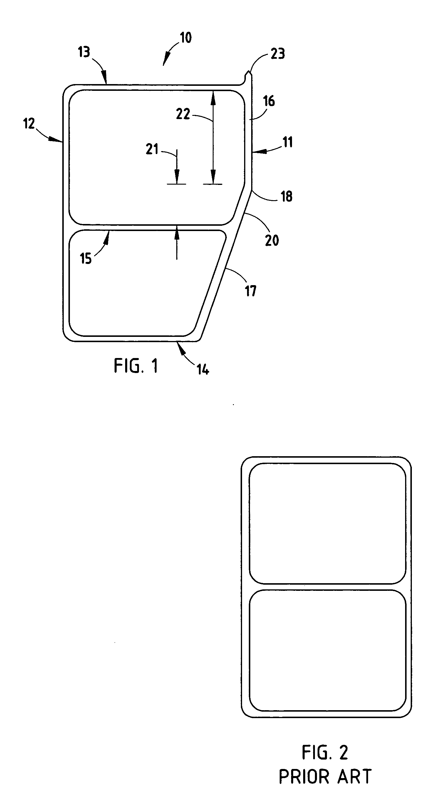
[0017] For purposes of description herein, the terms “upper,”“lower,”“right,”“left,”“rear,”“front,”“vertical,”“horizontal,” and derivatives thereof shall relate to the invention as oriented in FIG. 1. However, it is to be understood that the invention may assume various alternative orientations, except where expressly specified to the contrary. It is also to be understood that the specific devices and processes illustrated in the attached drawings, and described in the following specification are simply exemplary embodiments of the inventive concepts defined in the appended claims. Hence, specific dimensions and other physical characteristics relating to the embodiments disclosed herein are not to be considered as limiting, unless the claims expressly state otherwise.

[0018] A vehicle bumper beam 10 (FIG. 1) includes front, rear, top and bottom walls 11-14, and a reinforcement wall 15 that define upper and lower tubes. Notably, although the terms “front”, “rear”, “top”, and “bottom”...


PUM


Abstract

A vehicle bumper beam includes front, rear, top and bottom walls and a reinforcement wall that define upper and lower tubes. The front wall includes a vertical section, an angled section, and a bent section. The reinforcement wall supports the angled section below the bent section to provide predictable and desired energy absorption. The angled section preferably includes an angled portion defining a first vertical dimension in the first tube and the vertical section defining a second vertical dimension, with a ratio of the first and second being about 1:3. Also preferably, the front wall is at least about 3 mm and the remaining walls are less than about 2.0 mm thickness, or more preferably the exterior ones of the remaining walls are less than about 1.7 mm. In one embodiment, the upper and lower tubes are spaced apart.

Description

CROSS-REFERENCE TO RELATED APPLICATIONS [0001] This application claims benefit of provisional application Ser. No. 60 / 496,199, filed Aug. 19, 2003, entitled BUMPER BEAM HAVING FACE WITH SUPPORTED ANGLED WALL.BACKGROUND [0002] The present invention relates to vehicle bumper beams, and more particularly relates to a tubular beam constructed that is shaped for improved energy absorption and predictable collapse. [0003] Extruded and tubular bumper beams for modern passenger vehicles are known, including ones made from aluminum. However, extruding processes and materials often require thick sections to obtain the strengths required. Improvements are desired to decrease weight while maintaining energy absorption. Further, improvements are desired to improve a consistency and predictability of energy absorption upon collapse. Still further, optimization of particular beam shapes is desired to facilitate manufacture, while accomplishing the above objectives. [0004] Thus, a bumper system hav...

Claims


Application Information

Patent Timeline
Patent Type & Authority Applications(United States)
IPC IPC(8): B60R19/18
CPCB60R2019/182B60R19/18
Inventor REIERSON, DAVID E.JOHNSON, THOMAS J.
Owner SHAPE CORP
Why Eureka
Try Eureka