Method of controlling hardening with laser beam and laser beam hardening device

Inactive Publication Date: 2005-07-26
YAMAZAKI MAZAK KK
View PDF9 Cites 4 Cited by
  • Summary
  • Abstract
  • Description
  • Claims
  • Application Information

AI Technical Summary

Benefits of technology

[0010]Accordingly, the laser beam output power is lower at the scanning peaks, where the relative velocity of the laser beam over the surface of the workpiece is relatively lower, as compared to the laser beam output power near the center line, where the beam output power and the scan velocity are higher. This tends to equalize the applied energy per unit of area and to improve hardening.
[0046]By placing the oscillating beam scanning means between the beam splitter and the condensing lens, the beam splitter is located upstream of the oscillating beam scanning means. The reflected light used to determine temperature is captured correctly and the temperature can be determined accurately for various positions through which the laser beam is scanned.

Problems solved by technology

Such temperature control is not conventionally executed in a laser beam hardening device.
But it is difficult using such a sensor to trail the point at which the laser energy is applied.
The method is not practical because the torch device for applying the laser beam energy has a complicated track along which the laser beam is oscillated spatially, namely scanning at least partly lateral to the feeding direction or path along which hardening is to proceed, over a length and width as well as to some three-dimensional hardening depth.
The radiation applied per unit area may be too high at phase positions where the relative velocity of the beam is low, as to melt the workpiece locally.
On the other hand, the radiation energy per unit area may be too low at positions where the relative velocity of the beam is high, as to fail to raise the temperature of the workpiece to the level desired for hardening.
Proper hardening is not possible unless the beam power and the scan velocity together achieve the desired material temperature.

Method used


Image

  • Method of controlling hardening with laser beam and laser beam hardening device
  • Method of controlling hardening with laser beam and laser beam hardening device
  • Method of controlling hardening with laser beam and laser beam hardening device

Examples


Embodiment Construction

[0057]Embodiments of the invention are explained hereinafter with reference to the accompanying drawings.

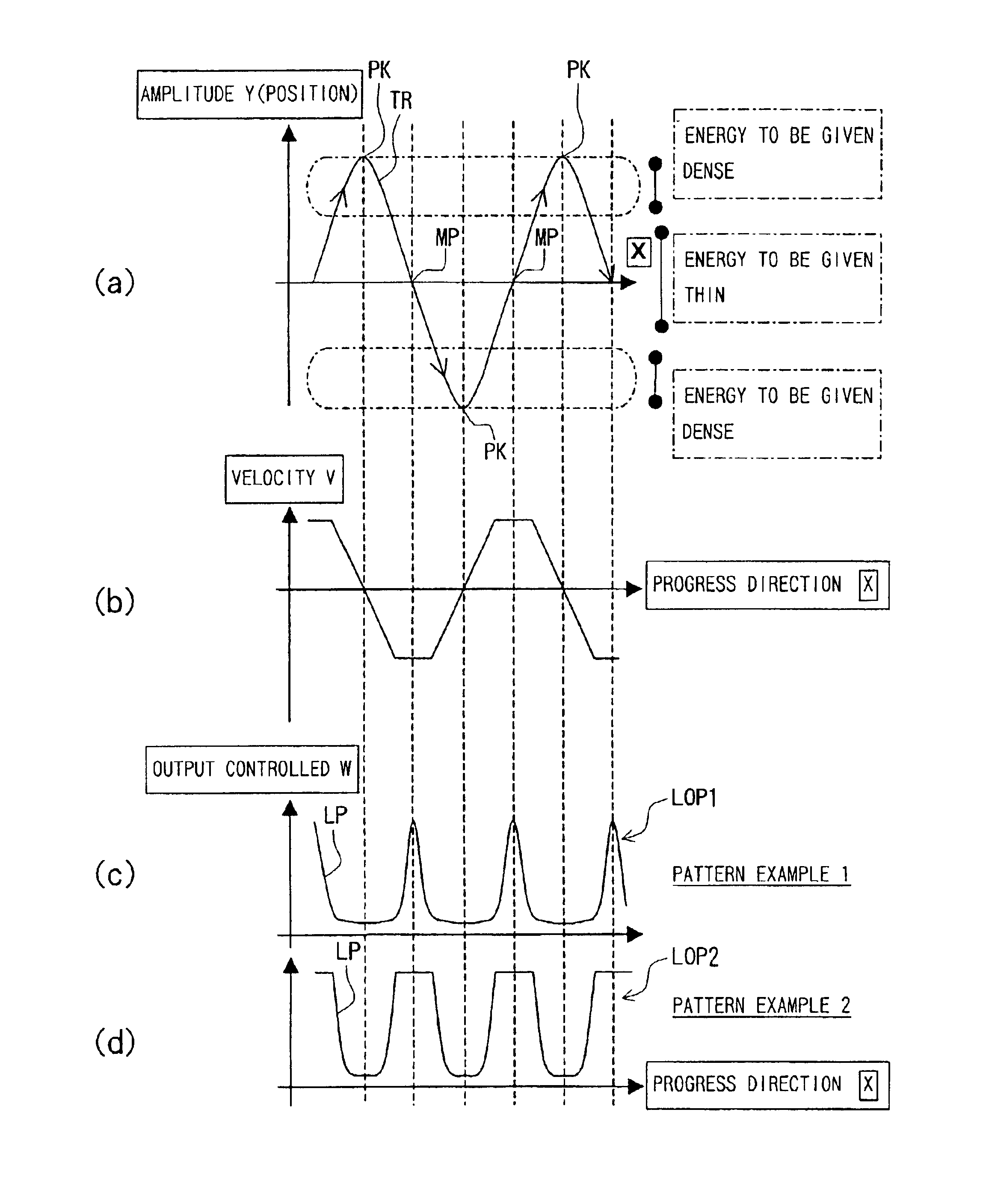
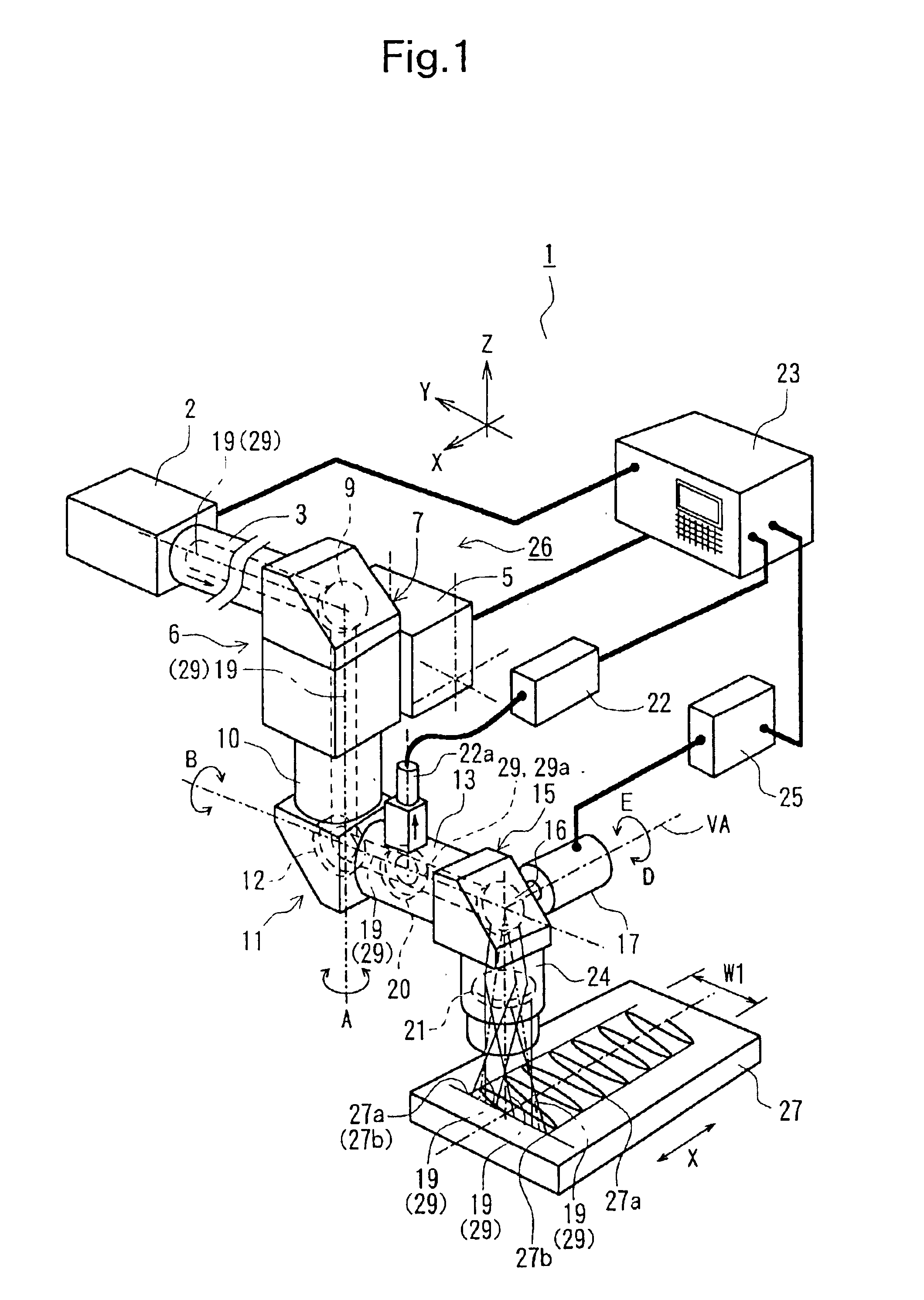
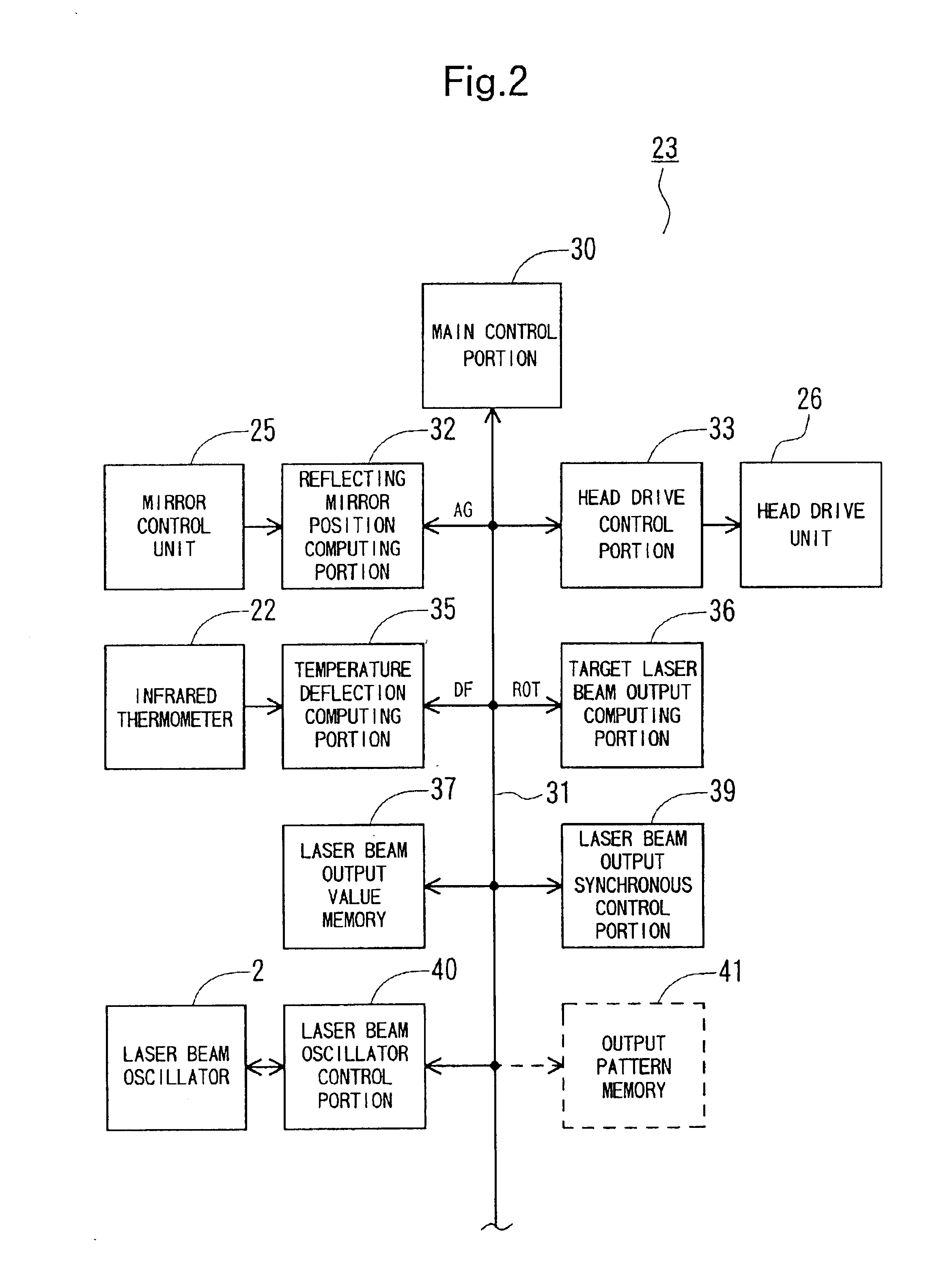
[0058]FIG. 1 is a schematic perspective view showing elements of a laser beam hardening device to which the present invention is applied. FIG. 2 is a block diagram for showing important portions and connections in a numerical-control (NC) version of the unit. FIG. 3 is a schematic view demonstrating a re-circulating laser beam output value memory. FIG. 4 shows an oscillating scanning track over which the laser beam is passed to harden an associated area. FIG. 5 is a schematic view for showing contents of respective data blocks in a laser beam output value memory. FIG. 6 is a series of corresponding time plots wherein (a) shows the scanning track of the laser beam (a full hardening cycle); (b) shows the scan velocity of the laser beam over the workpiece, corresponding to (a); (c) illustrates an exemplary varying laser beam output power pattern for the scan in (a); and (d) shows an...


PUM

PropertyMeasurementUnit
Temperatureaaaaaaaaaa
Poweraaaaaaaaaa
Energyaaaaaaaaaa

Abstract

A workpiece is irradiated by a laser beam scanned in an oscillating track as the workpiece is advanced along a feed path in a hardening process. Sinusoidal variations in scan velocity are offset by decreasing the laser beam power level at phases in the scanning cycles corresponding to high and low scan displacement peaks, where the scan velocity is least. The beam power is increased near the scanning center line where the scan velocity is highest. The beam energy applied per unit of area is thus equalized over the scanning cycle. The workpiece temperature can be sampled at regular phases by a non-contact temperature sensor in the optical path, and used to control beam power versus phase in a subsequent scanning cycle. Alternatively or in addition, a sinusoidal beam power pattern can be stored and used to offset scan velocity variations as a function of phase.

Description

BACKGROUND OF THE INVENTION[0001]This invention relates to a method of controlling material hardening using a laser beam, and the associated laser beam hardening device. The inventive method and device are capable of correctly measuring and controlling the temperature of a portion of material to be hardened, while scanning the laser over the material in an oscillating motion, and controlling the laser output power level from one hardening cycle to a next.[0002]A method of hardening workpiece along a path with a predetermined width, by spatially oscillating the laser beam in a direction intersecting a feeding direction has been recently proposed. It is necessary correctly to detect the temperature of a portion to be hardened and to control the temperature of the portion to obtain proper hardening.[0003]Such temperature control is not conventionally executed in a laser beam hardening device. It is possible to envision a method of measuring the temperature of a portion of material to b...

Claims


Application Information

Patent Timeline
IPC IPC(8): B23K26/42B23K26/00B23K26/06B23K26/08C21D1/09C21D11/00
CPCB23K26/0626B23K26/0807B23K26/0846B23K26/426B23K26/428C21D1/09C21D11/00B23K26/082B23K26/705B23K26/707B23K26/352
Inventor YAMAZAKI, TSUNEHIKOMIYAGAWA, NAOOMIINOUE, TOSHIHIKOASARI, TOSHIHIKOMATSUMURA, MASAARU
Owner YAMAZAKI MAZAK KK
Why Eureka
Try Eureka