Apparatus for repairing bright spot defects in display devices

A bright spot defect and equipment technology, applied in nonlinear optics, instruments, optics, etc., can solve problems such as differences in energy density of laser beams

Active Publication Date: 2015-07-29
苏州科韵激光科技有限公司
View PDF2 Cites 0 Cited by
  • Summary
  • Abstract
  • Description
  • Claims
  • Application Information

AI Technical Summary

Problems solved by technology

[0019] Therefore, there is a problem that the energy density of the laser beam irradiated to the position of each color filter has a difference

Method used


Image

  • Apparatus for repairing bright spot defects in display devices
  • Apparatus for repairing bright spot defects in display devices
  • Apparatus for repairing bright spot defects in display devices

Examples


no. 1 example 200

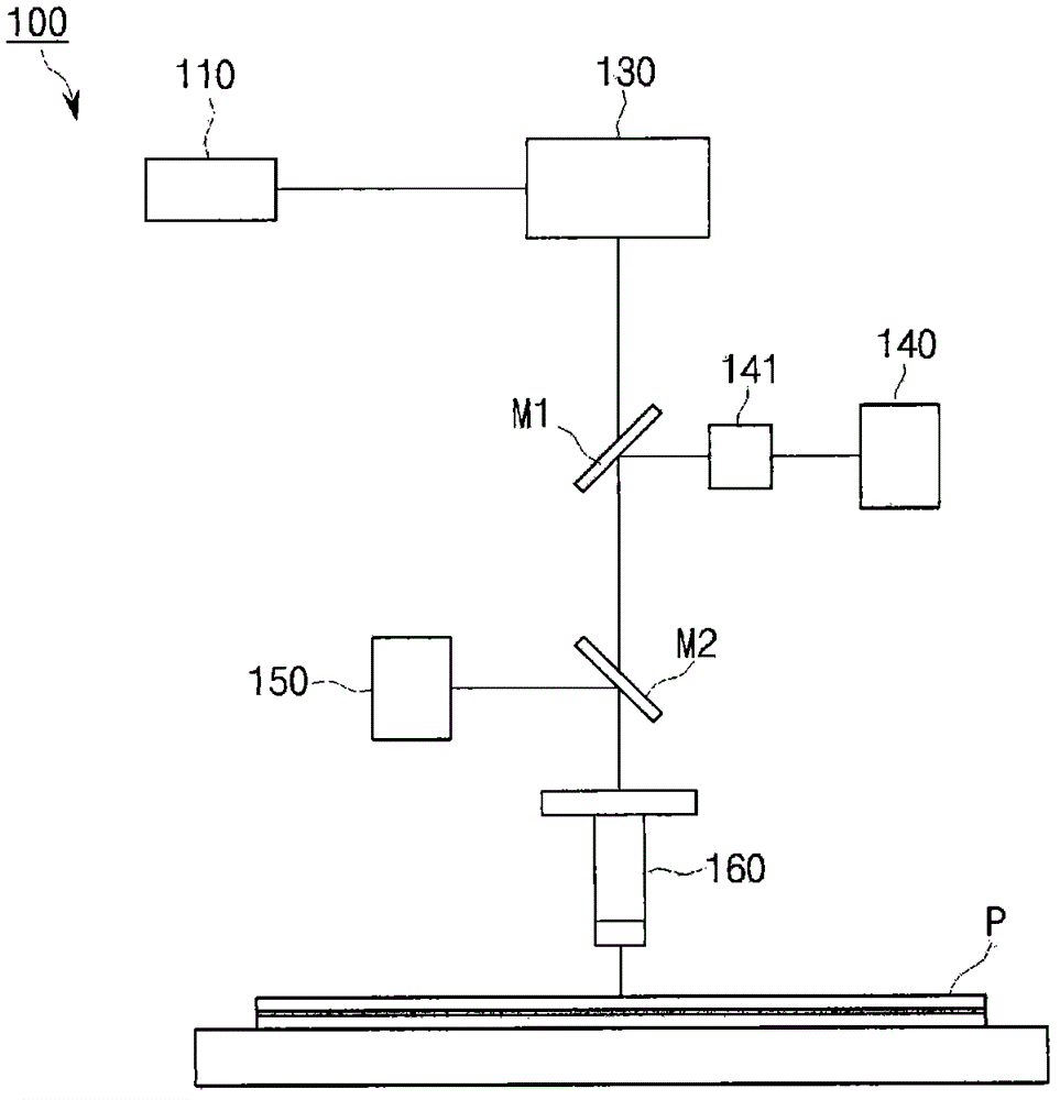
[0047] refer to Figure 7 As shown, the first embodiment 200 of the device for repairing bright spot defects according to the present invention includes a laser unit 210; a beam intensity adjustment unit 220 for adjusting the intensity of the laser beam irradiated by the laser unit 210; beam shape control Component 270; scanner 230 for scanning the laser beam in the irradiation area of ​​the color filter of panel P; beam processing surface control component 280; monitoring unit 240 and lighting 241 for real-time confirmation of color filter (or panel) and, the focus automatic adjustment member 250 and the focus lens 260 are used to adjust the focus of the laser beam. In addition, a plurality of mirrors M1 and M2 for controlling the path of light are further arranged in the device.

[0048] The scanner 230 is a well-known component, and includes: an X galvanometer mirror and a Y galvanometer mirror for changing the direction of the laser beam; and a scanning lens for collectin...


PUM


Abstract

The present invention relates to an apparatus for repairing a bright point defect in a display device, and more particularly, to an apparatus for repairing a bright point defect in a display device having a uniform laser beam energy density across the entire scope of a laser radiation area. The apparatus for repairing a bright point defect according to the present invention comprises: a laser part for radiating a laser beam onto a color filter having a bright point defect; a scanner for scanning the laser beam in a radiation area of the color filter; and beam-processing surface control means for filtering and preventing the scanned laser beam from being radiated onto the color filter in an acceleration section or a deceleration section.

Description

technical field [0001] The present invention relates to a device for repairing bright spot defects of a display device, in particular, relates to a device for repairing bright point defects of a display device. The energy density of the laser beam is uniform throughout the laser beam irradiation area. Background technique [0002] Recently, a liquid crystal display device has attracted attention as a next-generation cutting-edge display device, which has low power consumption, good portability, technology-intensive, and high added value. Among such liquid crystal display devices, especially an active matrix type liquid crystal display device (including a switching element capable of switching a voltage applied to each pixel) has attracted the most attention due to its excellent resolution and video processing capability. [0003] refer to figure 1 As shown, the structure of a common liquid crystal panel 500 is that a color filter substrate as an upper substrate and a thin f...

Claims


Application Information

Patent Timeline
Patent Type & Authority Patents(China)
IPC IPC(8): G02F1/1335G02F1/13
CPCG02F1/1309G02F1/1313
Inventor 金僊株辛相孝金政宪姜翼俊
Owner 苏州科韵激光科技有限公司
Why Eureka
Try Eureka