Jointing head for fastening element, and a fastening method

a technology of fastening element and fastening head, which is applied in the field of joining head, can solve the problems that the fastening element held by the gripper is not optimally aligned with the hardening source, and achieve the effect of preventing mechanical overload

Inactive Publication Date: 2014-01-23
BOLLHOFF VERBINDUNGSTECHNIK GMBH
View PDF4 Cites 7 Cited by
  • Summary
  • Abstract
  • Description
  • Claims
  • Application Information

AI Technical Summary

Benefits of technology

[0017]It is also preferable to equip the jointing head with a damping unit which is connected to the gripper. This damping unit dampens mechanical overloading at the jointing head arising from an incorrect feed movement of the jointing head in the jointing direction toward the component surface. According to another preferred embodiment, this damping unit comprises a passive or active linear adjustment of the gripper so that the gripper can be moved...

Problems solved by technology

Consequently, the fastening element held by the gr...

Method used


Image

  • Jointing head for fastening element, and a fastening method
  • Jointing head for fastening element, and a fastening method
  • Jointing head for fastening element, and a fastening method

Examples


Embodiment Construction

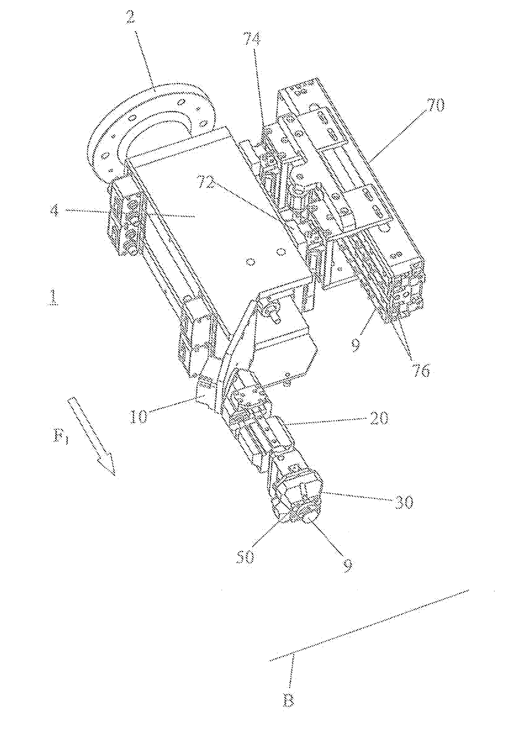
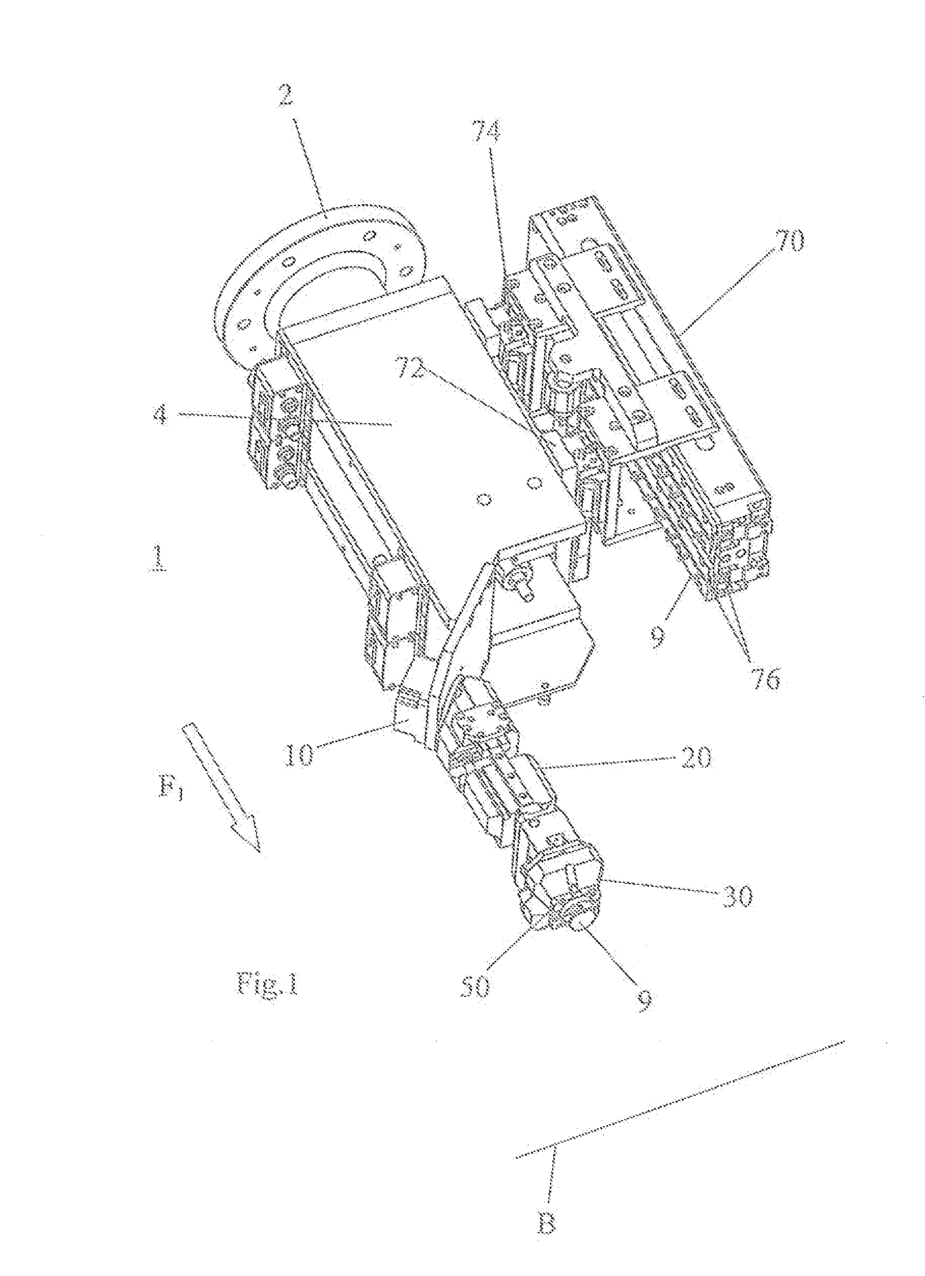
[0030]A preferred embodiment of the jointing head 1 according to the invention is shown in FIG. 1. The jointing head 1 comprises an attachment or fastening plate 2 for connecting the jointing head 1 to a robot or an automated jointing machine (not shown). The jointing head 1 is preferably used in combination with a 6-axis robot. It is also conceivable to use a robot with 2 to 5 axes in combination with the jointing head 1.

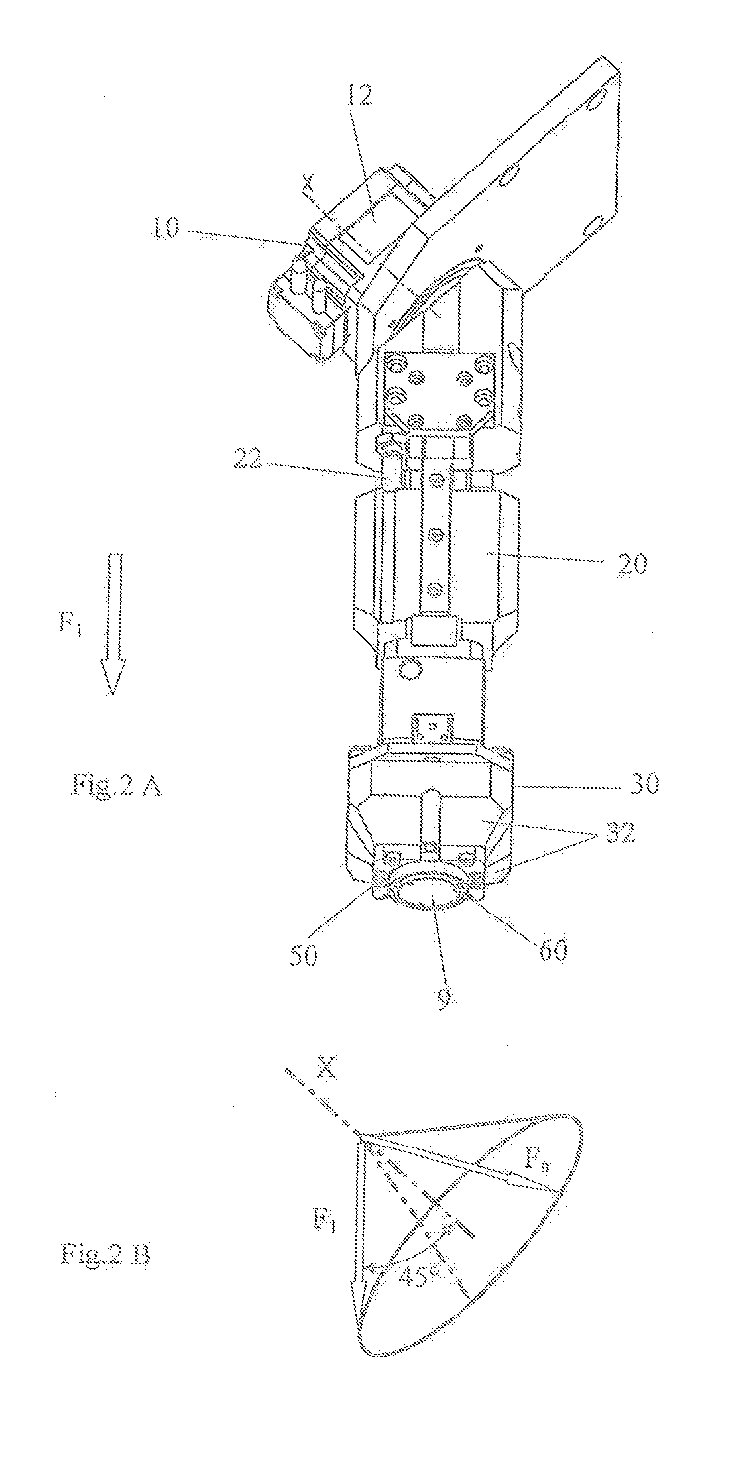
[0031]A support or intermediate piece 4 abuts the fastening plate 2. A cartridge 70 as well as a gripper arm 20 with a gripper 30 is fastened to this intermediate piece 4. The gripper 30 and gripper arm 20 can be swung by a swinging or pivoting mechanism to the cartridge 70. The gripper arm 20 with the gripper 30 assumes a jointing position (see FIG. 1) parallel to a first jointing direction F1, or a swung position (see FIG. 10) perpendicular to the first jointing direction F1 for removing a fastening element 9 from the cartridge 70. Based on the pivoting movement ...


PUM

PropertyMeasurementUnit
Angleaaaaaaaaaa
Distanceaaaaaaaaaa

Abstract

The present invention comprises a jointing head 1, a robot with this jointing head 1, and a fastening method for affixing fastening elements 9 to a component surface B. The jointing head 1 comprises a gripper 30 that removes fastening elements 9 from a removal position E of a cartridge 70 by means of a pivoting movement. In addition, the jointing head 1 comprises a compensation mechanism 40 of the gripper 30 so that, when the fastening element 9 is mounted on a component surface B, the fastening element 9 is optimally arranged adjacent to a hardening source 60 such as a light source.

Description

FIELD OF THE INVENTION [0001]The present invention relates to a jointing head that automatically affixes fastening elements to a component surface by means of a robot or automatic jointing machine. In addition, the present invention relates to a robot connected to this jointing head, as well as a method for affixing the fastening element to a component surface that is realizable with the assistance of this jointing head.BACKGROUND OF THE INVENTION [0002]Within industry, adhesive fastening elements are increasingly being used that hold components and functional parts. Such fastening elements consist for example of a T-shaped structure when looking at the cross-section of these fastening elements. This T-shaped structure comprises a plate-shaped fastening surface to which a bolt-like element with a variable design is fastened. This bolt-like element has for example a thread, a snap connection or any other structures. The plate-like element provides a fastening surface to which adhesiv...

Claims


Application Information

Patent Timeline
IPC IPC(8): F16B11/00
CPCF16B11/00B23P19/006F16B11/006Y10T156/17B23P19/00B23Q7/04
Inventor DRUKE, FRANZNOBBENHUIS, ANDRE HERMANNDRAHT, TORSTENLOSCHNER, CARSTEN
Owner BOLLHOFF VERBINDUNGSTECHNIK GMBH
Why Eureka
Try Eureka