Crack detection system

Active Publication Date: 2009-10-22
SIEMENS GAMESA RENEWABLE ENERGY AS
View PDF2 Cites 29 Cited by
  • Summary
  • Abstract
  • Description
  • Claims
  • Application Information

AI Technical Summary

Benefits of technology

[0010]The fibres used in fibre Bragg grating systems have, as already mentioned, a diameter of about 120 μm. Moreover, these fibres are extremely fragile. Compared to these fibres, the fibres with a diameter below 75 μm are less fragile and their dimensions are comparable with the dimensions of the fibres in a typical glass fibre laminate. Hence, the fibres with diameters below 75 μm are more robust than those fibres used in fibre Bragg grating system and are in particular useful for use in a fibre reinforced laminated structure such as, e.g., a shell of a wind turbine rotor blade.
[0011]In order to increase their capacity of transmitting light the fibres can be led through the structure in form of fibre bundles. Such bundles can consist of up to several hundred single fibres which makes the system even more robust as a higher number of fibres gives redundancy to the system and making it, therefore, less vulnerable.
[0012]A further advantage of bundling fibres is that in case of an emerging crack not all fibres of a bundle do necessarily brake at the same time. When more and more fibres of the bundle brake, the transmission of light through the fibre bundle decreases. This is a simple and robust way to measure degradation of the engineering structure, which is, in particular useful if the degradation comes slowly. However, even if a crack develops rapidly a determination of the sequence of breaking of the fibres in a bundle can give hints on the development of the crack which may be useful in evaluating the crack.
[0013]As single fibres with diameters below 75 μm, e.g., with diameters of about 50 μm, are used, the bundle is compatible with the surrounding fibres if the engineering structure is made

Problems solved by technology

Cracks and failures in such loaded engineer

Method used


Image

  • Crack detection system
  • Crack detection system
  • Crack detection system

Examples


Embodiment Construction

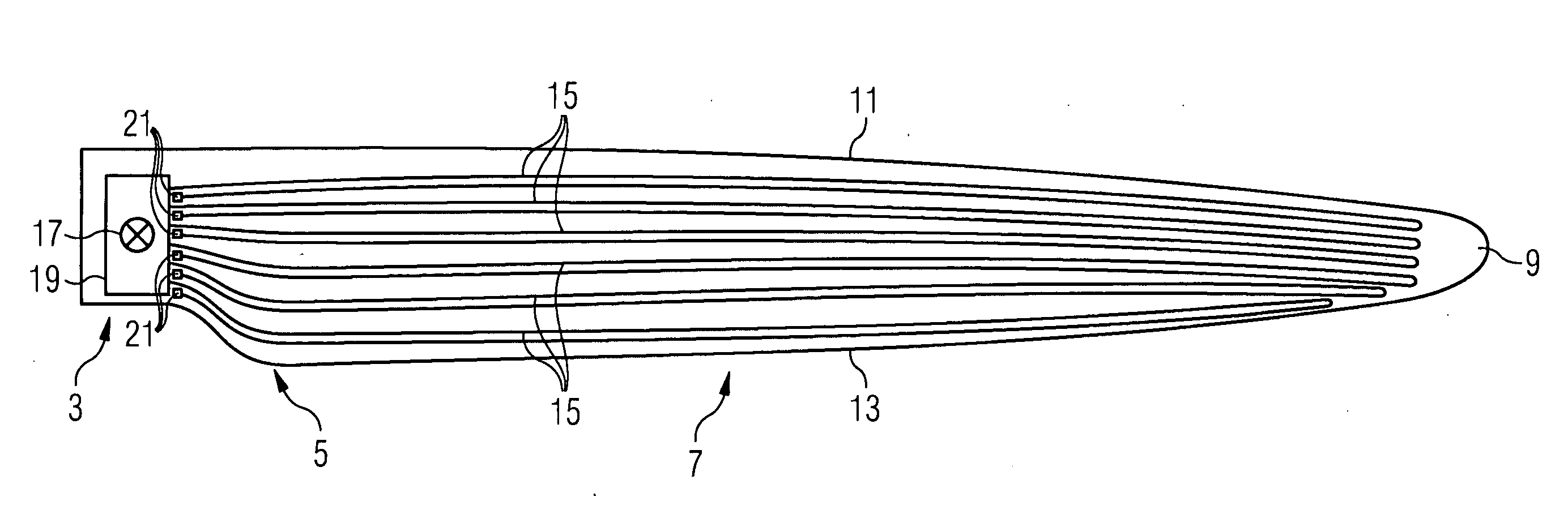
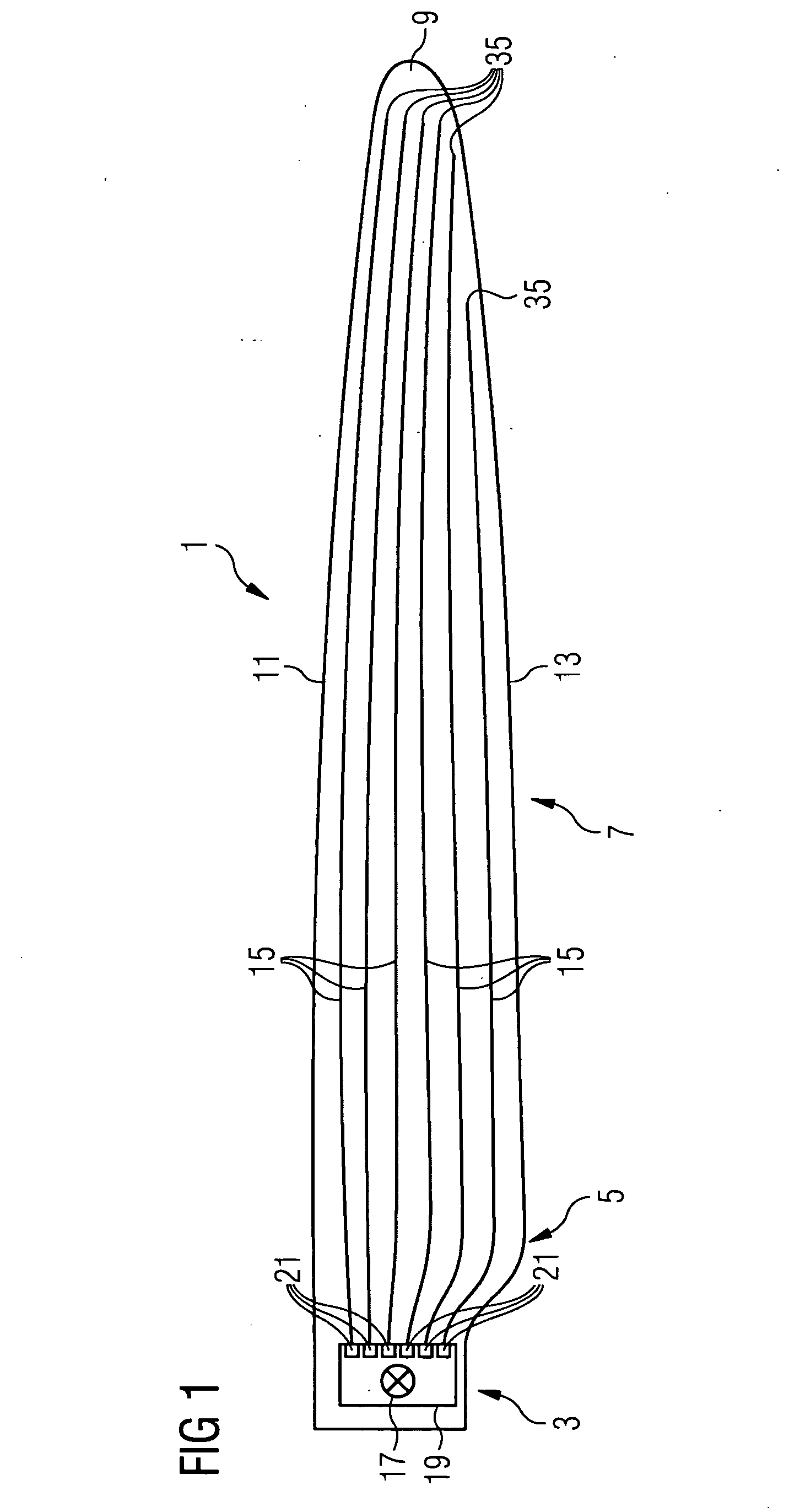
[0037]FIG. 1 shows a first embodiment of an inventive crack detection system in a wind turbine rotor blade. Note that the wind turbine rotor blade is only an example for an engineering structure in which the crack detection system can be used.

[0038]The wind turbine rotor blade 1 shown in FIG. 1 comprises a root section 3, a shoulder 5 which adjoins the root section in outward direction of the blade, and an airfoil section 7 which extends from the shoulder 5 to the blade's tip 9. Furthermore, the blade 1 comprises a leading edge 11 and a trailing edge 13.

[0039]The blade shown in FIG. 1 is equipped with an inventive crack detection system. The crack detection system comprises a plurality of optical fibre bundles 15 in which the single fibres have diameters below 75 μm, a light source 17 which is, in the present embodiment, located in the root section of the blade 1, and a means 19 for coupling the light of the light source into the fibre bundles 15. The means for coupling the light in...


PUM


Abstract

A crack detection system and a method for detecting cracks in a loaded engineering structure are provided. The system and method include a light source coupled and optical fibres that are led through the structure. The optical fibres have diameters below 75 μm. The light source is coupled to the optical fibres.

Description

CROSS REFERENCE TO RELATED APPLICATIONS[0001]This application claims priority of European Patent Office application No. 08007726.6 EP filed Apr. 21, 2008, which is incorporated by reference herein in its entirety.FIELD OF INVENTION[0002]The present invention relates to a crack detection system for detecting cracks in a loaded engineering structure. The loaded engineering structures can be, e.g., a wind turbine rotor blade, an airplane wing, a propeller, a helicopter rotor, a structural car part, a concrete building, a concrete water dam, etc.BACKGROUND OF INVENTION[0003]Cracks and failures in such loaded engineering structures can have severe consequences. Early warning of a propagating crack can save lives and property.SUMMARY OF INVENTION[0004]A method and a device by which it is possible to detect cracks in a wind turbine rotor blade is disclosed in WO2006 / 012827A1. A device for monitoring the state of rotor blades on wind power installations measures the structure-borne noise by...

Claims


Application Information

Patent Timeline
IPC IPC(8): G01B11/16G02B6/00
CPCF03D11/00F05B2260/80F05B2270/404G01M5/0016Y02E10/722G01M5/0091G01M11/086Y02B10/30G01M5/0033F03D17/00
Inventor BURCHARDT, CLAUSGROVE-NIELSEN, ERIKKRISTENSEN, JENS JORGEN OSTERGAARDSTIESDAL, HENRIK
Owner SIEMENS GAMESA RENEWABLE ENERGY AS
Why Eureka
Try Eureka