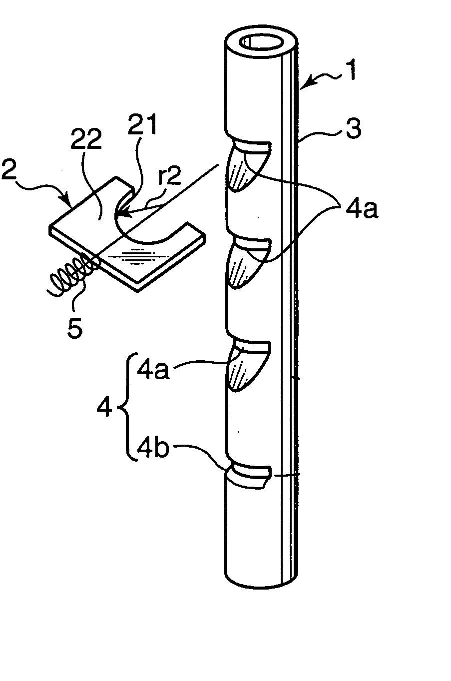
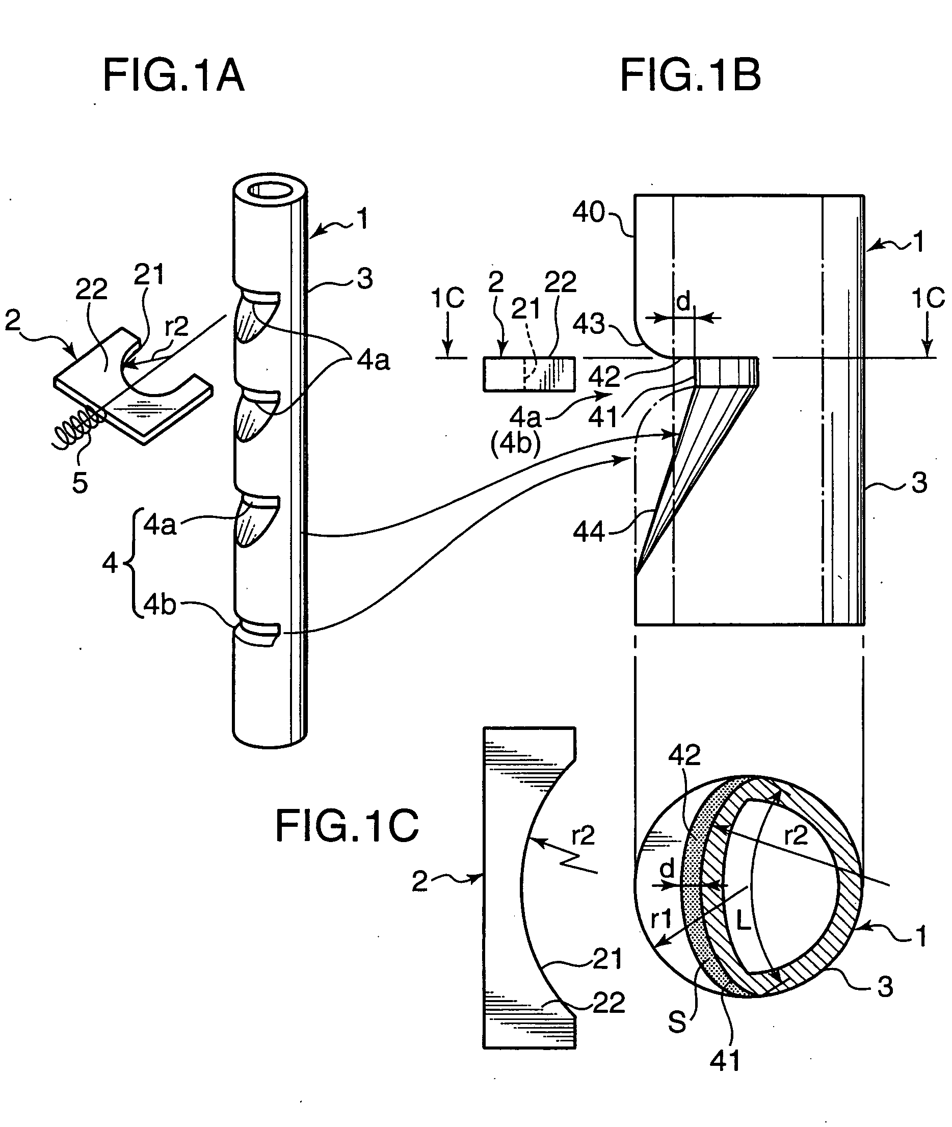
[0014] According to an aspect of the invention, a headrest lock structure is provided with a plurality of lock slots formed in a cross-sectionally circular headrest pole in a line along the axial direction of the headrest pole, and a lock member adapted to be fitted into either one of the lock slots. Each of the lock slots has a bottom surface protruding in an arc shape within a region concaved from the outer
peripheral surface of the headrest pole by a given distance; and a side surface formed on at least one of the sides of the bottom surface in the axial direction of the headrest pole to extend outwardly from the bottom surface within the region at an approximately right angle with the bottom surface.
[0013] In view of the above circumstances, it is therefore an object of the present invention to provide a headrest lock structure with lock slots, a method of forming such lock slots in a headrest pole, and a method of producing such a headrest pole which are free from the problems residing in the prior art.
[0028] For example, a long, cross-sectionally circular
pipe member 3 made of stainless steel or iron is used as a material pole. The
pipe member 3 is subjected to a press-forming process to form a plurality (four in this embodiment) of lock slots 4 therein in a line along the axial direction of the pipe member 3. The cross-sectional shape of the pipe member (or an after-mentioned
solid member 30) is not limited to a circular shape, but may be any other suitable shape, such as a square or rectangular shape.
[0029] Among the lock slots 4, the lower most lock slot 4b has a shape different from that of the upper three lock slots 4a, because while each of the lock slots 4a has a shape allowing the height of a headrest to be freely adjusted depending on the
body type of an occupant or other factor, the lock slot 4b is required to have a shape for preventing a headrest from unintentionally coming off. This reason will be described in more detail later.
[0014] According to an aspect of the invention, a headrest lock structure is provided with a plurality of lock slots formed in a cross-sectionally circular headrest pole in a line along the axial direction of the headrest pole, and a lock member adapted to be fitted into either one of the lock slots. Each of the lock slots has a bottom surface protruding in an arc shape within a region concaved from the outer
peripheral surface of the headrest pole by a given distance; and a side surface formed on at least one of the sides of the bottom surface in the axial direction of the headrest pole to extend outwardly from the bottom surface within the region at an approximately right angle with the bottom surface.
[0014] According to an aspect of the invention, a headrest lock structure is provided with a plurality of lock slots formed in a cross-sectionally circular headrest pole in a line along the axial direction of the headrest pole, and a lock member adapted to be fitted into either one of the lock slots. Each of the lock slots has a bottom surface protruding in an arc shape within a region concaved from the outer peripheral surface of the headrest pole by a given distance; and a side surface formed on at least one of the sides of the bottom surface in the axial direction of the headrest pole to extend outwardly from the bottom surface within the region at an approximately right angle with the bottom surface.
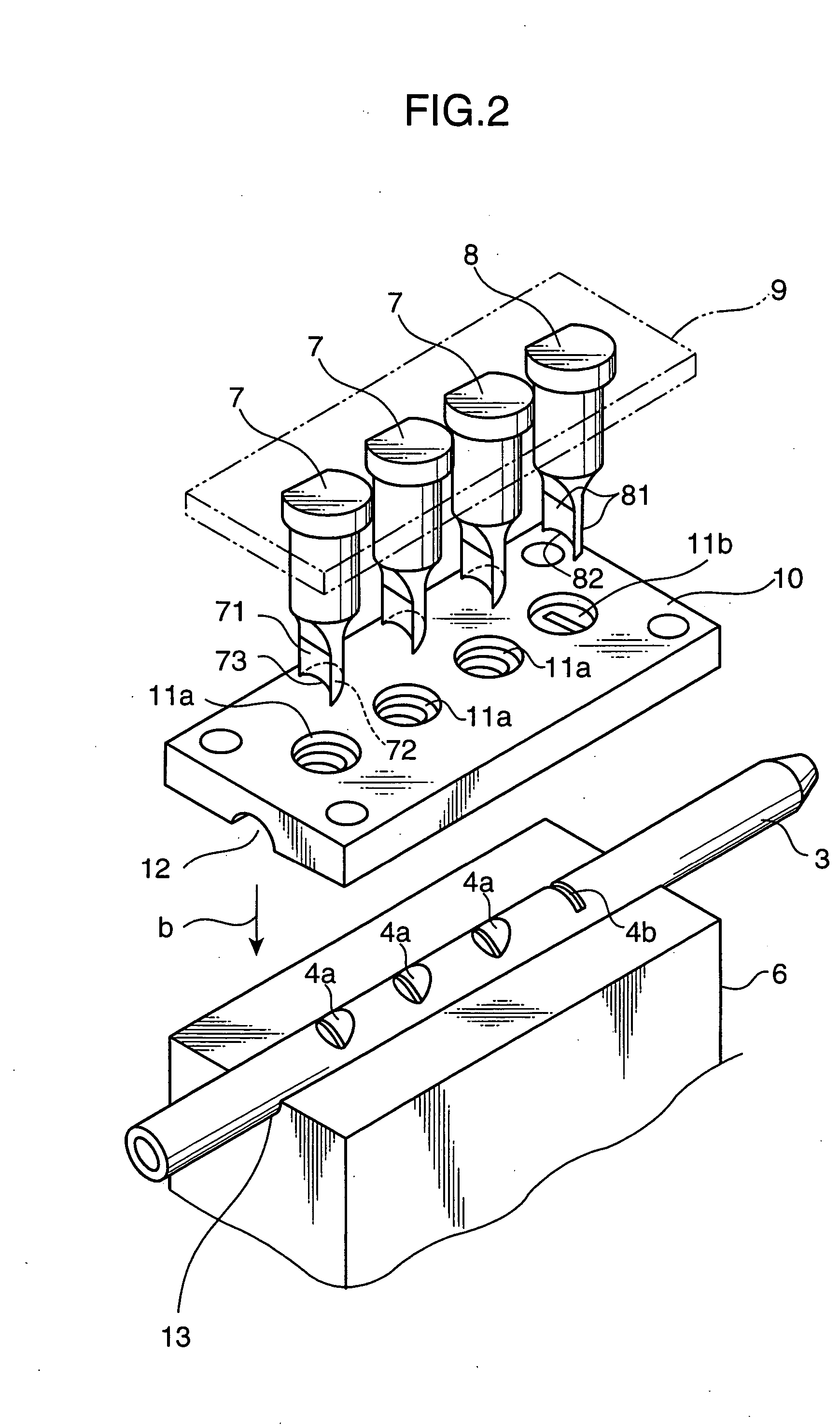
[0033] For example, the lock slots of the headrest pole in the above headrest lock structure may be formed through the following method. Referring to FIG. 2 showing a manner of forming the lock slots in the headrest pole, and FIG. 3 illustrating the positional relation between a punch and the associated lock slot, viewing from the upper surface of the punch, a pipe member 3 for use as a material pole is first
cut to have a given length, and horizontally placed on a press base 6. Then, a punch guide 10 formed with guide holes 11a, 11b for punches 7, 8 (pressing tool) at given positions is placed on the press base 6 to cover over a portion of the outer peripheral surface of the pipe member 3. In FIG. 2, the reference numerals 12 and 13 indicate a pair of semicircular grooves corresponding to the profile of the pipe member 3 to be subjected to a press-forming process. The grooves 12, 13 act to disperse a pressing force applied to the pipe member 3 so as to suppress the deformation in a portion of the pipe member 3 other than portions to be formed as the lock slots 4. In this state, the punches 7, 8 held by a punch holder 9 are moved downwardly (in a direction indicated by the arrow “b”) and pressed against the outer peripheral surface of the pipe member 3 to form the lock slots 4 (4a, 4b) in the pipe member 3.
[0046] While the headrest pole 1 in the above embodiment is produced using a cross-sectionally circular pipe member 3 as a material pole, a cross-sectionally circular
solid member 30 consisting of a
metal bar may also be used as a material pole, as shown in FIGS. 5A to 5C. In this case, the
solid member may be subjected to a
cutting process to form the lock slots 4 therein so as to eliminate the arc-shaped portion (sagging portion) 43 (see FIG. 1) and achieve substantial increase in the maximum width “d” of the upper side surface 42 and the area of the engagement region S to further reliably prevent the unintentional release of headrest lock. Alternatively, the headrest pole 1 may be produced through a
forging process, or may be produced by molding a resin material.
