Electric motor

a technology of electric motors and gears, applied in piezoelectric/electrostrictive device details, piezoelectric/electrostrictive devices, device details, etc., can solve problems such as one dimension limitation and complex arrangement of motors and gears

Inactive Publication Date: 2005-04-21
JOHNSON ELECTRIC SA
View PDF9 Cites 19 Cited by
  • Summary
  • Abstract
  • Description
  • Claims
  • Application Information

AI Technical Summary

Problems solved by technology

Hence the one dimension limitation.
In the past, this

Method used


Image

  • Electric motor
  • Electric motor
  • Electric motor

Examples


Embodiment Construction

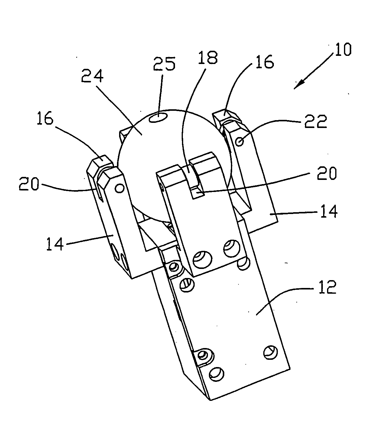
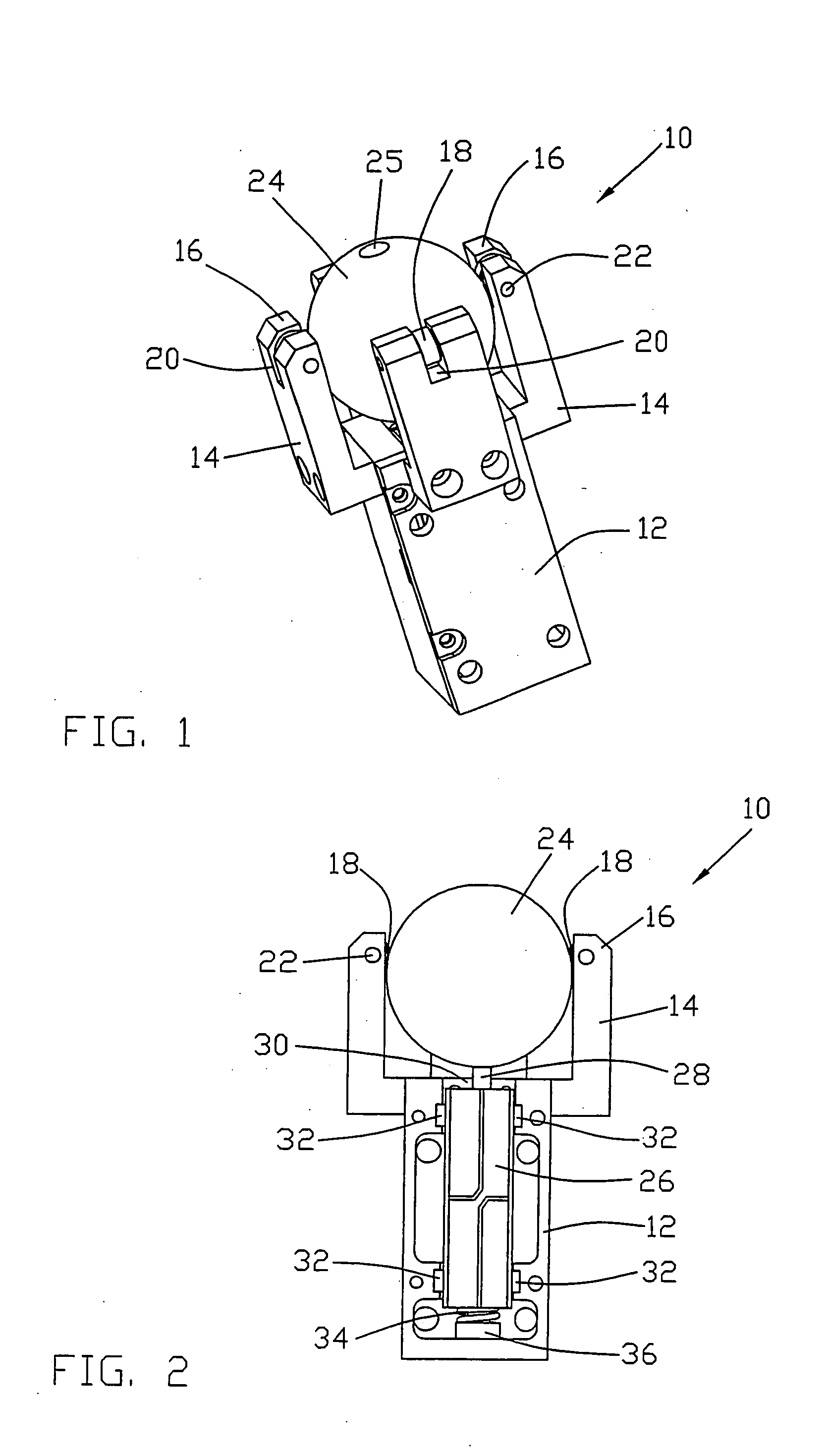
[0029]FIG. 1 illustrates conceptually a motor 10 designed according to a preferred embodiment of the present invention. FIG. 2 is a partial sectional view of the motor 10 of FIG. 1. The motor 10 of FIG. 1 has a housing 12 looking like a rectangular prism.

[0030] Extending like raised arms from adjacent the upper end of the housing 12 are four L-shaped supports 14. Each support has a slotted distal end 16. A disc or roller 18 is held in each slot 20 by a pin 22. The pins 22 are offset inwardly to allow the rollers 18 to extend into the space between the supports 14 without extending outwardly of supports.

[0031] Within the area defined by the supports is located a spherical ball 24. The ball 24, supports 14 and rollers 18 are sized so that the ball is held captive within the supports by the rollers 18 which contact the ball 24 above its median line, i.e. the rollers contact the ball at spaced locations within an upper hemisphere as viewed in FIG. 1. The ball 24 is the rotor or slider...


PUM


Abstract

A piezoelectric motor has an actuator 26 which drives a slider 24. The actuator has a rectangular steel core of square cross-section with an axially projection driving tip 28. A ceramic piezoelectric element 40 is bonded to each of the four faces of the core. Each piezoelectric element has four quadrants covered by quadrant electrodes 40a-40d on one side and a common or earth electrode on the other side contacting the core which electrically joins the common electrodes. By selective excitation of corresponding diagonally opposite quadrants of opposite piezoelectric elements, the actuator is made to drive the tip in either the X direction or the Y direction. The preferred slider is a spherical ball held captive within arms extending from a housing of the actuator. The driving tip is pressed against the ball by a preload spring 34 acting on the actuator. Operation of the actuator causes the ball 24 to rotate about an X axis or about a Y axis producing a two dimensional movement from a single motor and single actuator.

Description

CROSS-REFERENCE TO RELATED APPLICATIONS [0001] This non-provisional patent application claims priority under 35 U.S.C. § 119(a) from Patent Application No. 0323920.9 filed in Great Britain on Oct. 11, 2003. FIELD OF THE INVENTION [0002] This invention relates to an electric motor and in particular, to an electric motor using piezoelectric ceramics. BACKGROUND OF THE INVENTION [0003] Piezoelectric motors, using piezoelectric ceramics to effect linear or rotary motion are well known. As with a magnet motor, these ceramic motors effect motion in only one dimension, i.e., for a linear motion, back and forth along a line and for rotary motion, clockwise or anti-clockwise about a single axis or line. Hence the one dimension limitation. [0004] However, at times, it is desirable to move an object in more than one dimension, more than just back and forth or rotate clockwise and anti-clockwise. In the past, this required a complex arrangement of motors and gears. SUMMARY OF THE INVENTION [000...

Claims


Application Information

Patent Timeline
IPC IPC(8): H02N2/00H01L41/09
CPCH02N2/004H02N2/108H02N2/103
Inventor LI, GUO WEICHEN, FENG DONGCHENG, KAI
Owner JOHNSON ELECTRIC SA
Why Eureka
Try Eureka