Extended range interferometric refractometer

Inactive Publication Date: 2000-10-03
WYATT TECH
View PDF3 Cites 39 Cited by
  • Summary
  • Abstract
  • Description
  • Claims
  • Application Information

AI Technical Summary

Problems solved by technology

Even though this method may be of use in measuring a large refractive index difference of a sample sufficient to produce a plateau, the technique cannot be used to monitor the instantaneous refractive index changes following a chromatographic separation.
Indeed, the Phillips et al. approach will only be successful if a single plateau is obtained and the sample is not fractionated before the measurement.
This results in the two beams having the same polarization and interfering with one another in a simple manner.
The main problem with this structure is the non-symmetry of the recombining two beams because of the half wave plate placed into one of them.
Since only one beam goes through the Pockels cell, there is no easy method for drift cancellation.
Frot et al. point out that all earlier type of interferometric device by Couillard , U.S. Pat. No. 4,787,746, whose design objectives were similar to theirs and which used a Piezo electric modulator, will not be as stable since the latter can drift due to heating and cause a resultant drift in the measurement with time.
They associate the mechanical motion of the Piezo electric driven mirror as being a potentially unpredictable and non compensated heat source.
The second problem is that the sensitivity goes to zero when the argument of the arccos gets near .+-.1.
Although many light sources are provided

Method used


Image

  • Extended range interferometric refractometer
  • Extended range interferometric refractometer
  • Extended range interferometric refractometer

Examples


Embodiment Construction

Although the preferred embodiment of this invention makes use of a liquid crystal retarder to follow the rotation of the elliptically polarized beam's major axis, there are two other implementations that could achieve this. We will discuss briefly two of these implementations: a split beam structure and a rotating analyzer.

Split Beam

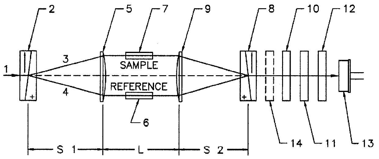
FIG. 7 shows the configuration of a split beam implementation to follow the rotation of the emerging combined beam. After the recombined beam emerges from the second Wollaston prism 8, it is split by a partially silvered mirror, prism, or pellicle means 17 into two beams 18 and 19 of nearly equal intensity. Each beam then goes through its own quarter wave plate 20 and 21, polarization analyzer 22 and 23, and detector 24 and 25. The two analyzers are set at 45 degrees physical angle to one another, corresponding to 90 degrees phase in the output signal. The analyzers may be rotated initially to determine the maximum and minimum intensity as described for ...


PUM


Abstract

A method and apparatus is disclosed for measuring the refractive index difference between a reference and sample liquid based on an interferometric design. The resultant device has an almost unlimited range of operation in contrast to a conventional interferometric refractometer of the so-called polarization type whose dynamic range is restricted to a relatively narrow range of refractive indices. The measurement of the refractive index difference between a sample and reference cell is achieved by measuring the angle through which the plane of polarization of a combined beam has rotated. For the conventional device, this angle is restricted to about pi radians which corresponds to a half wavelength shift between the reference and sample components of said combined beam. The extended range device disclosed permits this angle to be tracked and measured accurately over many rotations. The rotation tracking is achieved by one of three embodiments, the preferred of which involves the use of a liquid crystal retarder. The other two techniques incorporate, respectively, a rotating polarizer and a doubly split beam. All three embodiments permit the measurement of both the sine and cosine of the rotation angle and, thereby, allows a four quadrant arctangent calculation to yield the rotation angle directly. The error associated with such measurements is not a function of the rotation angle of the combined beams.

Description

BACKGROUND AND NEED FOR THE INVENTIONDifferential refractometers are widely used as detectors for the chromatographic analysis of a broad range of chemical compounds including polymers, pharmaceuticals, and food products. Concentrations of solutes of 10.sup.-6 to 10.sup.-8 g / ml are commonly detected. Differential refractometers produce a signal which is proportional to the difference of the refractive index between at sample and a reference solution. The reference is usually a pure solvent. In the limit of vanishingly small solute concentration dc, the variation of the sample refractive index dn is defined to be dn / dc. This value is dependent on both the dissolved compound and the solvent, and must be determined in order to relate the instrument refractive index change to the instantaneous solute concentration. Once the value of dn / dc is known at a particular wavelength for a particular compound and solvent, the refractometer can be used as an absolute concentration detector. If the...

Claims


Application Information

Patent Timeline
IPC IPC(8): G01N21/41G01N21/45
CPCG01N21/45
Inventor JANIK, GARY R.SHEPARD, DOUGLAS W.TRAINOFF, STEVEN P.PHILLIPS, DAVID T.
Owner WYATT TECH
Why Eureka
Try Eureka