Bidirectional power flow efficient energy saving converter

A high-efficiency energy-saving, power flow technology, applied in the field of frequency converter, can solve problems such as failure to work normally, low dynamic performance, grid voltage waveform distortion, etc., and achieve good low-frequency starting characteristics, good static and dynamic characteristics, and improve power factor.

Inactive Publication Date: 2008-01-16
上海神源电气有限公司
View PDF0 Cites 37 Cited by
  • Summary
  • Abstract
  • Description
  • Claims
  • Application Information

AI Technical Summary

Problems solved by technology

This way not only wastes energy, but also pollutes the environment
In addition, since the input current of the rectifier is the charging current for the electrolytic capacitor E1, the current waveform is not a sine wave, and the high-order harmonic content is quite large. The power factor of this inverter is low, causing many adverse effects, such as: Occupying the power grid Capacity; pollute the power grid, cause the voltage waveform distortion of the power grid, make other equipment on the line unable to work normally, etc.
Again, the space voltage vector control method for driving the PWM inverter is based on the steady-state mathematical model of the asynchronous motor, and the dynamic performance is not high

Method used


Image

  • Bidirectional power flow efficient energy saving converter
  • Bidirectional power flow efficient energy saving converter
  • Bidirectional power flow efficient energy saving converter

Examples


Embodiment Construction

[0013] Below in conjunction with accompanying drawing and specific embodiment the present invention is described in further detail:

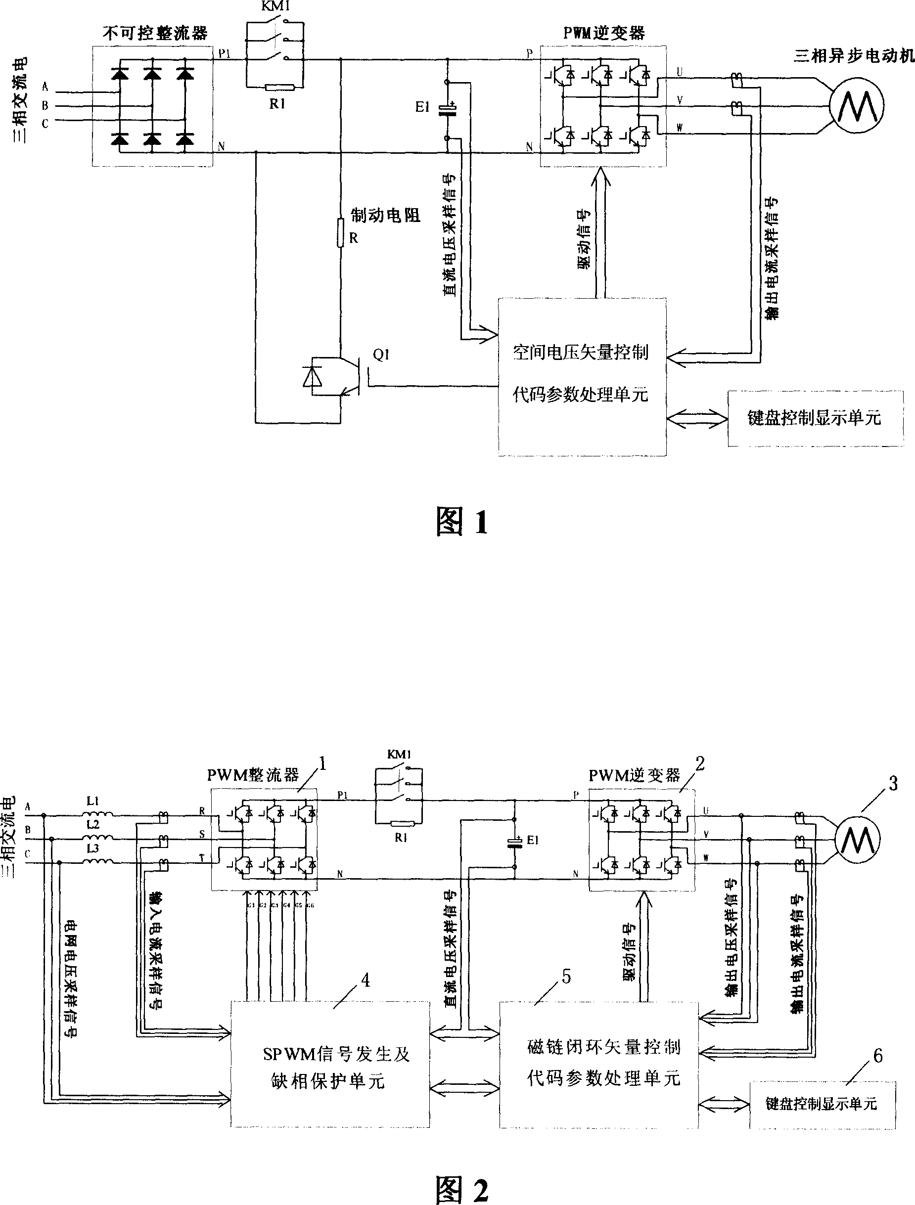
[0014] As can be seen from Fig. 2, the present invention includes: PWM inverter 2, electrolytic capacitor E1, contactor KM1, asynchronous motor 3, keyboard control display unit 6; The first inductance L1, the second inductance L2, and the third inductance L3 are respectively connected to the R, S, and T terminals of the PWM rectifier 1, and the P1 terminal of the PWM rectifier 1 is connected to the three input contacts of the contactor KM1, and the three terminals of the contactor KM1 The first output contact is connected to the P terminal of the PWM inverter 2, the resistor R1 is connected in parallel with the contactor KM1, the N terminal of the PWM rectifier 1 is connected to the N terminal of the PWM inverter 2, and the positive electrode of the electrolytic capacitor E1 is connected to the PWM inverter 2 The P terminal of the electrolytic c...


PUM


Abstract

The invention relates to an energy-efficient bidirectional power flow transducer provided with a topological structure for dual PWM frequency conversion main circuit, combining three-phase PWM rectifying with three-phase PWM inverting to achieve a four-quadrant controlled transducer and realize bidirectional energy transmission between the power network and the motor. The power network can directly get electric energy feedback and braking torque can be adjusted automatically when power generation is delivered so that environmental protection and power saving can be realized. The great improvement of power factor both can effectively inhibit electromagnetic interference, harmonic pollution and can reduce switching loss. The entire systemis provided with double closed loop vector controlled scheme and adaptive function, is characterized in good static and dynamic performance and low frequency starting.

Description

technical field [0001] The invention relates to a frequency converter, in particular to a frequency converter capable of realizing bidirectional transmission of energy between a grid and a motor, high power factor and high efficiency and energy saving. Background technique [0002] Most of the existing frequency converters adopt general-purpose frequency converters whose structure is uncontrollable rectification-DC-inversion, and the control method is space voltage vector. [0003] But this frequency converter has some disadvantages. Firstly, when the motor decelerates or the driven potential energy load is lowered, the motor is in the state of generating power, and the six feedback diodes of the inverter inverter feed back this power to the DC side, because the unidirectional flow of the uncontrolled rectifier makes the power It cannot be returned to the grid, which will cause the DC bus voltage of the inverter to rise and fail to work normally. Therefore, in order to kee...

Claims


Application Information

Patent Timeline
Patent Type & Authority Applications(China)
IPC IPC(8): H02M7/758H02M7/66
Inventor 钱匡胡新宇任海松童建立
Owner 上海神源电气有限公司
Why Eureka
Try Eureka