
Determining a coverage mask for a pixel

a technology of determining and pixel, applied in the field of determining for a pixel, can solve the problems of inability to eliminate total, inability to accurately define edges, image aliasing, etc., and achieve the effect of reducing storage space, adequate edge smoothing, and reducing storage requirements

Inactive Publication Date: 2006-02-28
RPX CORP
View PDF8 Cites 40 Cited by
  • Summary
  • Abstract
  • Description
  • Claims
  • Application Information

AI Technical Summary

Benefits of technology

[0056]It is an advantage of the invention that it reduces the storage space required for storing the coverage masks significantly, since only a quarter of the coverage masks have to be stored compared to prior art solutions. At the same time, the invention does not increase the number of required computations for the coverage mask look up.
[0057]It is moreover an advantage of the invention that it allows an adequate smoothing of edges at all angles, and that it does not discard any fragments whatever their size.
[0058]It is equally an advantage of the invention that it is very versatile. It can be applied for example irrespective of the size of the stored coverage masks, and irrespective of the number of the stored coverage masks.
[0059]In a preferred embodiment of the invention, each stored coverage mask is associated to a combination of an edge vector of a specific orientation in the first quadrant and of a specific distance of a vector to the center of a respective pixel. In this case, the distance between the original edge vector and the center of the pixel is determined in addition. A stored coverage mask is then fetched, which is associated on the one hand at least indirectly to the transposed edge vector and on the other hand to the distance determined for the original edge vector. It is an advantage of the invention that it can be applied irrespective of the metric used to measure the position of the edge relative to the currently processed pixel's center.
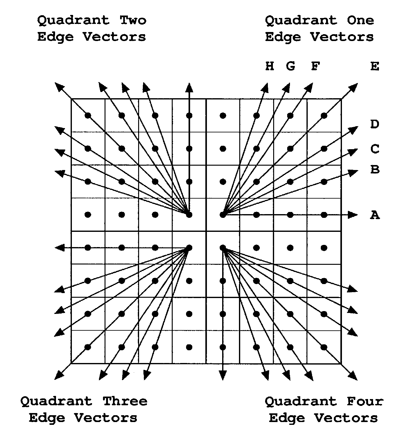
[0060]In a further preferred embodiment of the invention, the invention is employed for determining a coverage mask for each edge of the geometric primitive. The resulting coverage masks for all edges can then be combined to a single coverage mask for a respective pixel. Such a combined coverage mask represents the extend of coverage of the pixel by the geometric primitive. This extend can then be used for modifying the color of the pixel in a known manner. As the storage requirements are reduced, the invention also provides the possibility for edge-level parallelism by replicating the coverage masks look up scheme for every edge of the geometric primitive, and thus for increasing the performance and reducing the power consumption of the antialiasing. In a further preferred embodiment of the invention, representative edge vectors having different, predetermined orientations are defined. The representative edge vectors are distributed by these predetermined orientations in a “rotationally symmetric” manner to the four quadrants of the Cartesian coordinate system. That is, if the set of representative edge vectors defined for one quadrant is rotated in steps of 90°, the resulting edge vectors correspond exactly to the set of another quadrant. In this case, one of the representative edge vectors in the predetermined quadrant is selected, which has a similar orientation as the transposed edge vector. Then a stored coverage mask is fetched, which is associated to the selected representative edge vector and thereby indirectly to the transposed edge vector. Since the final occupation of a coverage mask is determined making use of a “rotational symmetry”, a 100% occupation of two adjacent primitives is achieved, and a pixel color can therefore be determined accurately in all situations.
[0061]In a further preferred embodiment of the invention, the predetermined orientations for the representative edge vectors are selected such that the representative edge vectors are distributed uniformly over an angle-related space, e.g. the dex(α) space, to the four quadrants. Thereby, the accuracy of a coverage value indicating the extend of the coverage of a pixel by a geometric primitive, which is determined based on the invention, is higher than the accuracy of a coverage value obtained in the prior art. Also, such an adjusted distribution does not result in any deflection from the 100% occupation of two adjacent primitives due to the “rotational symmetry”.

Problems solved by technology

If this process is not carried out properly, the resulting image suffers from aliasing.
The aliasing phenomenon creates undesirable visual artifacts known as “jaggies” or “staircasing” effect for the edges of the primitive, resulting in imprecise edges, as “popping” effect for very small primitives which are moving across the screen, or as a “flickering” of the presented image.
It is to be noted that a total elimination is not theoretically possible.
The second component is an aliasing due to an incorrect or inadequate reconstruction of the displayed image from the generated samples.
While many antialiasing techniques have been proposed, there are no practical effective solutions to succeed in removing both aliasing components causes at once.
The post-filtering hardware algorithms have increased computation and storage costs due to the multiple sample approach.
Moreover, they result in certain situations in image artifacts due to the inadequate sampling rate, since the continuous object space often contains infinite spatial frequencies.
Therefore, the method chosen for primitive rasterization will impose limitations on the type of a pre-filtering antialiasing algorithm that can be efficiently implemented in hardware in conjunction with the rasterization engine.
The main drawback of this approach relates to the fact that it cannot handle line ends properly.
Analytic expressions for line ends are again difficult to derive, and a separate, more complex indexing scheme is required for that with less precise two-dimensional lookup tables.
The computational complexity increases further, when the antialiasing of the triangle's vertices, i.e. of the points where two line ends will intersect, or the antialiasing of triangles smaller than a pixel, i.e. where multiple line ends and vertices exist, are considered making the traditional approach of rasterization less attractive when used in conjunction with the antialiasing algorithms based on pre-filtering.
It is a drawback of the antialiasing algorithms with pre-filtering based on the traditional rasterization method that it is difficult to achieve an accurate antialiasing of the triangle corners and that it is computationally expensive.
It is also a drawback of this approach that the triangle traversal order is imposed by the scan conversion algorithm.
This makes it very difficult to generate several fragments in parallel in a random order and it makes implementations impossible that generate fragments in a tile rasterization order.
The traditional rasterization methods are not capable to make efficient usage of such hardware organizations.
Nevertheless, additional redundancy has to be built in the table.
Adjacent primitives which occupy other than 100% of the pixel lead to color errors like edge cracking.
Further, they do not favor any particular order of triangle traversal, which makes them well-suited for a tile rasterization order.
However, their hardware implementation, which is based on coverage mask lookup tables, is often inefficient.
The coverage mask lookup tables contain thousands of coverage masks that consume a considerable chip area.
This leads to a coverage mask lookup table time-sharing access approach and prevents an employment of low-power techniques that capitalize on parallel computation to reduce the activity factor inside the antialiasing circuitry.
Large lookup tables are of particular disadvantage for mobile devices.
Moreover, the large coverage mask lookup table content combined with the mechanism used to fetch the coverage mask during rasterization is a source of inaccuracies, which has to be minimized by additional measures.

Method used


Image

  • Determining a coverage mask for a pixel
  • Determining a coverage mask for a pixel
  • Determining a coverage mask for a pixel

Examples


Embodiment Construction

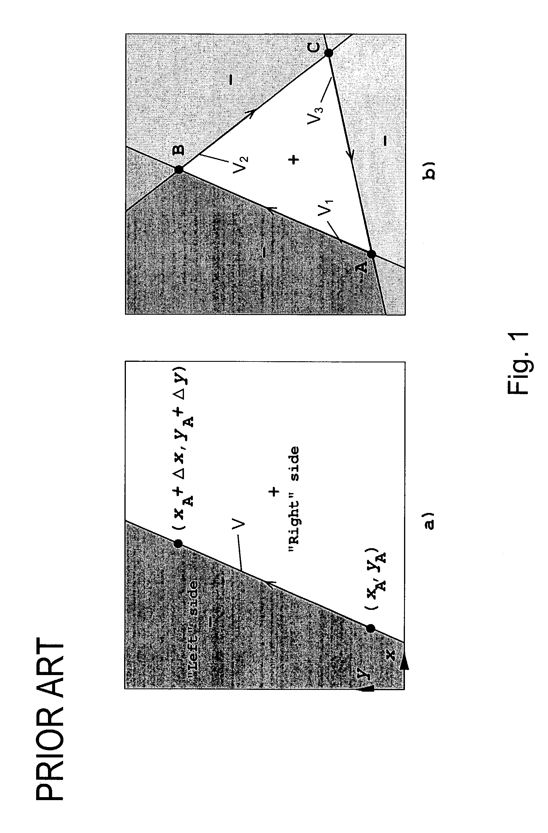
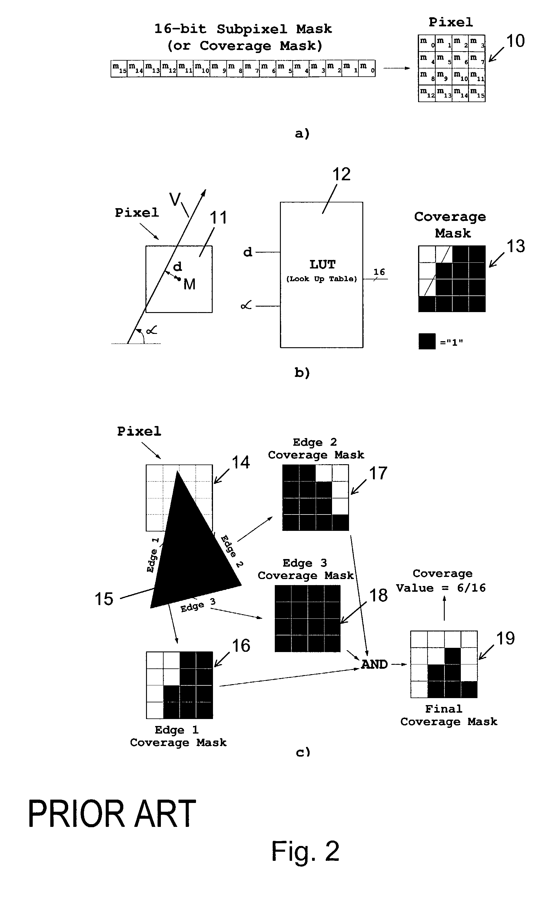
[0098]FIGS. 1 to 3 have been described above.

[0099]An embodiment of the method according to the invention will now be described with reference to FIGS. 4 to 12. The embodiment enables an antialiasing with pre-filering. More specifically, it allows to determine a coverage mask for an edge vector detected for a triangle by means of a look-up table. The edge vector is detected as in the above described prior art solutions employing a triangle rasterization with edge functions.

[0100]The presented embodiment makes use of the mathematical framework of the above cited documents “A Parallel Algorithm for Polygon Rasterization” and “A New Simple and Efficient Antialiasing with Subpixel Masks”, which are both incorporated by reference herein.

[0101]For the presented embodiment, a new edge vector class clusterization in the four quadrants of the plane is defined. This new clusterization is illustrated in FIG. 4.

[0102]FIG. 4 shows a first quadrant Q1, a second quadrant Q2, a third quadrant Q3 an...


PUM


Abstract

The invention relates to a method, a device, a system and a software program product for determining for a pixel a coverage mask reflecting an orientation and possibly a distance from the pixel center of an original edge vector. The pixel is to be employed for displaying at least a part of a geometric primitive on a display, and the original edge vector represents an oriented edge of the geometric primitive. The method comprises as a first step determining one of four quadrants of a Cartesian coordinate system to which the original edge vector belongs due to its orientation. The original edge vector is then transposed into a predetermined one of the four quadrants. Next, a stored coverage mask is fetched, which is associated at least indirectly to the transposed edge vector. Finally, the fetched coverage mask is transformed to the quadrant to which the original edge vector belongs.

Description

FIELD OF THE INVENTION[0001]The invention relates to a method for determining for a pixel a coverage mask reflecting an orientation, and preferably as well a distance from the pixel center, of an original edge vector. The pixel is to be employed for displaying at least a part of a geometric primitive on a display, and the original edge vector represents an oriented edge of the geometric primitive. The invention relates equally to a device, a system and a software program product for determining such a coverage mask.BACKGROUND OF THE INVENTION[0002]In computer graphics, images are displayed on a screen by a discrete grid of pixels. Each pixel represents a dot on the screen. Precisely defined geometric primitives from the continuous object space, like triangles, which are to be displayed on the screen thus have to be rasterized to pixel values. This process involves finding the pixels that are at least partially covered by the primitive and defining the color of the pixels. If a pixel...

Claims


Application Information

Patent Timeline
Patent Type & Authority Patents(United States)
IPC IPC(8): G09G5/00G06T7/00G06T11/20G06T11/40
CPCG06T11/203G06T11/40G06T2200/12G06T7/00G06T11/20G09G5/00
Inventor CRISU, DANCOTOFANA, SORINVASSILIADIS, STAMATISLIUHA, PETRI
Owner RPX CORP
Learn More