Hybrid multi-level current transformation topology based on H full-bridge subunit and control method of hybrid multi-level current transformation topology

A hybrid multi-level and sub-unit technology, applied in the direction of converting AC power input to DC power output, electrical components, output power conversion devices, etc., can solve the problem of large loss, high DC bus voltage level, complex control cascade H Bridge structure and other issues to achieve the effect of reducing system loss and system cost

Inactive Publication Date: 2012-06-27
INST OF ELECTRICAL ENG CHINESE ACAD OF SCI
View PDF7 Cites 36 Cited by
  • Summary
  • Abstract
  • Description
  • Claims
  • Application Information

AI Technical Summary

Problems solved by technology

[0004] The purpose of the present invention is to overcome the above-mentioned MMC structure and A2MC structure DC bus voltage level is high, the number of required cascaded power sub-units and IGBT is large, resulting in high system cost, large loss, complex control and cascaded H-bridge Due to the shortcomings of the structure that cannot share the DC bus and the application is limited, a new type of high-voltage and high-power multi-level converter topology and its control method that can share the DC bus and can realize four-quadrant operation are proposed.

Method used


Image

  • Hybrid multi-level current transformation topology based on H full-bridge subunit and control method of hybrid multi-level current transformation topology
  • Hybrid multi-level current transformation topology based on H full-bridge subunit and control method of hybrid multi-level current transformation topology
  • Hybrid multi-level current transformation topology based on H full-bridge subunit and control method of hybrid multi-level current transformation topology

Examples


Embodiment 1

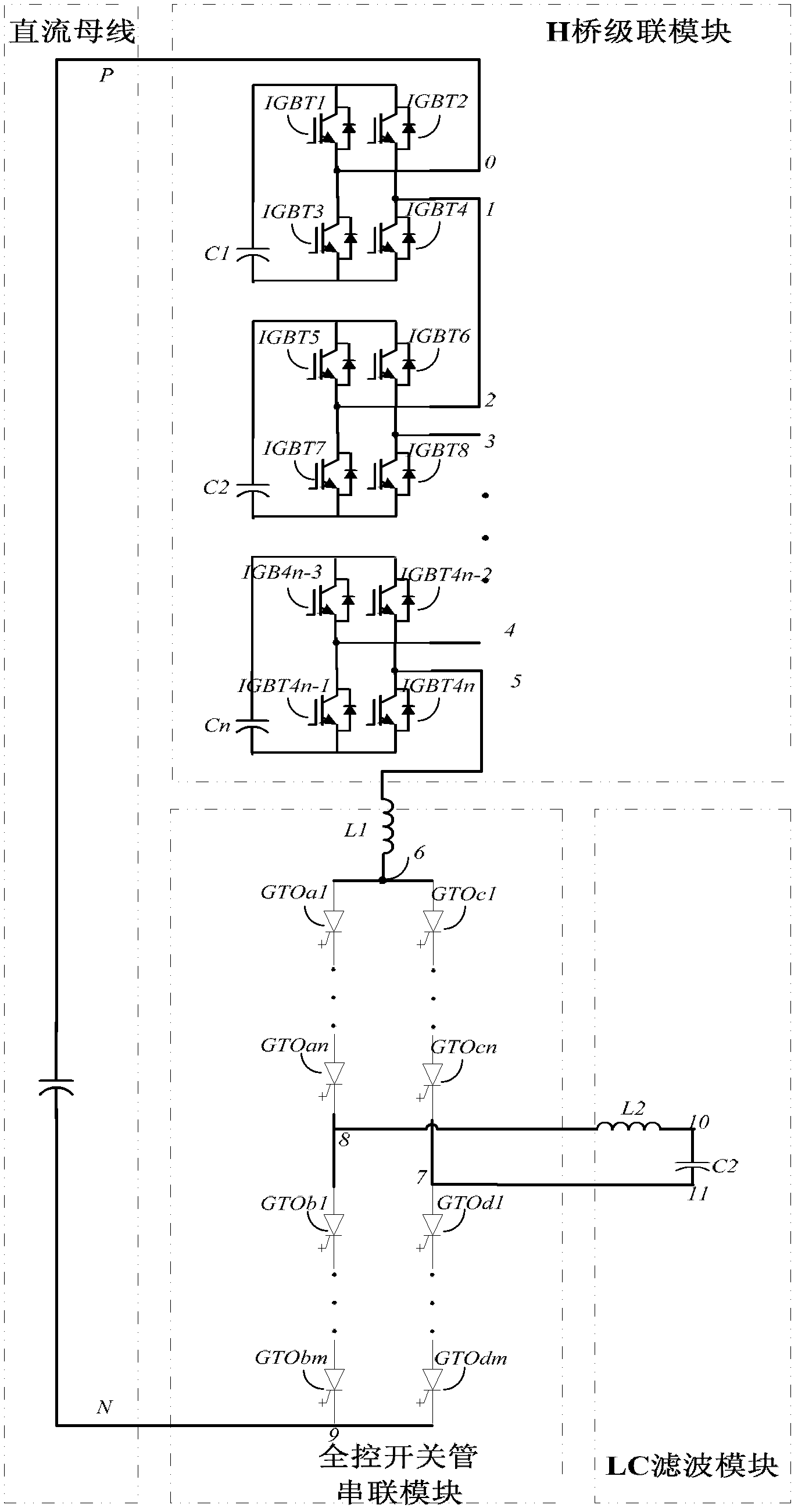
[0047] figure 1 Shown is the circuit schematic diagram of the embodiment of the hybrid multi-level converter topology based on the H full-bridge subunit of the present invention. The hybrid multi-level converter topology of the present invention includes: a DC bus, a single-phase converter circuit structure, and an LC low pass filter. One end of the H-bridge cascade module is connected to the positive DC bus, and one end of the full-control switching tube series module is connected to the negative DC bus. The single-phase inverter circuit structure includes H-bridge cascaded modules, connected inductors, and full-control switch tube series modules. The H-bridge cascade module is composed of n full-bridge subunits cascaded. The full-control switch tube series module consists of four bridge arms with the same structure to form an H-bridge circuit structure. In the H-bridge circuit, the first bridge arm of the full-control switch tube series module and the third bridge arm of t...

Embodiment 2

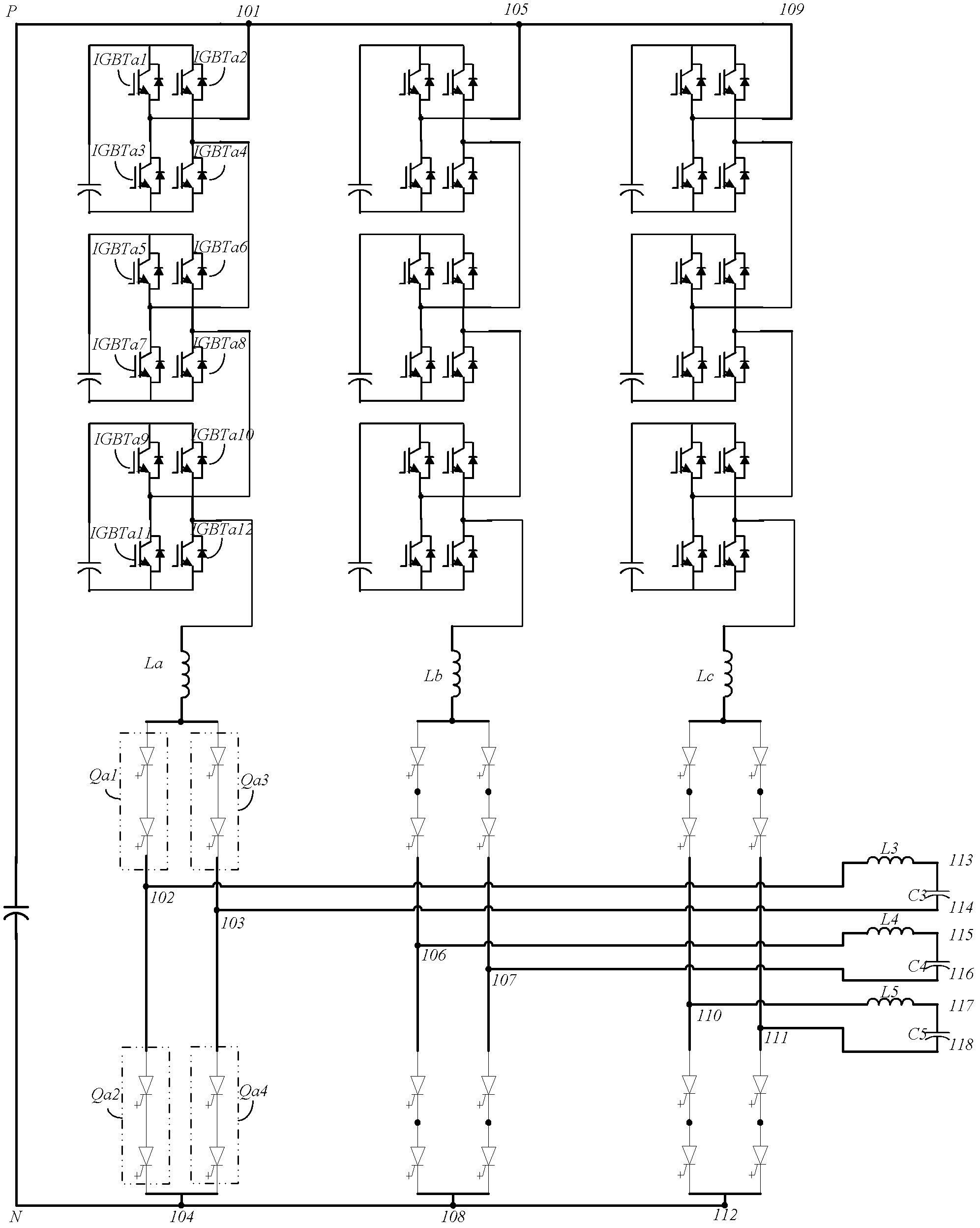
[0069] figure 2 Shown is a structural schematic diagram of a three-phase multi-level converter based on the single-phase converter topology of the present invention, including: a three-phase shared DC bus, three single-phase converter circuits, and a three-phase LC filter circuit. The three single-phase inverter circuits work on the same principle, and output a sine wave AC voltage with a mutual difference of 120 degrees. The topological structure of each single-phase converter circuit is the same as the single-phase converter topology in Embodiment 1 above. The first lead-out terminal 101 of the A-phase converter circuit, the first lead-out terminal 105 of the B-phase converter circuit, and the first lead-out terminal 109 of the C-phase converter circuit are connected to the positive DC bus P. The second lead-out terminal 104 of the A-phase converter circuit, the second lead-out terminal 108 of the B-phase converter circuit, and the second lead-out terminal 112 of the C-pha...

specific Embodiment

[0071] As a specific embodiment of a high-voltage high-power converter based on the H full-bridge power subunit of the present invention, the specific control method is as follows:

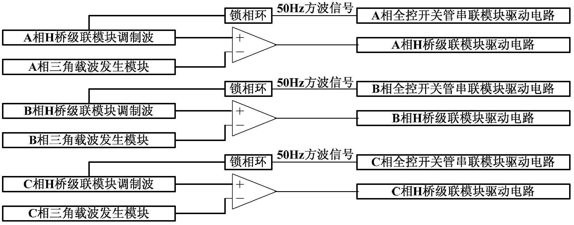
[0072] The control methods of phase A, phase B, and phase C are the same as the single-phase inverter topology described in Example 1, and the overall control method is as follows image 3 As shown, the modulation wave of the A-phase H-bridge cascade module is compared with the A-phase triangular carrier generation module, and the output modulation signal is sent to the drive circuit of the A-phase H-bridge cascade module, and the modulation wave of the A-phase H-bridge cascade module is output through the phase-locked loop The 50Hz square wave is sent to the A-phase full-control switch tube series drive circuit; the B-phase H-bridge cascade module modulation wave is compared with the B-phase triangular carrier generation module, and the output modulation signal is sent to the B-phase H-bridge casc...


PUM


Abstract

The invention relates to a hybrid multi-level current transformation topology based on an H full-bridge subunit, wherein one end of an H bridge cascading module is connected with a positive direct-current bus, and the other end of a fully-controlled switch tube series connection module is connected with a negative direct-current bus; the fully-controlled switching tube series connection module is of an H bridge circuit structure consisting of four bridge arms with same structure, wherein a connection point between the first bridge arm and the third bridge arm and a connection point between the second bridge arm and the fourth bridge arm are used as output terminals and connected with an LC low-pass filter; and one end of the H bridge cascading module is connected with a connection inductor, and the other end of the connection inductor is connected with one end of the fully-controlled switching tube cascading module. The hybrid multi-level current transformation topology disclosed by the invention can be used as a single phase, can be also used for a three-phase alternating-current circuit sharing a direct-current bus and realizes four-quadrant operation.

Description

technical field [0001] The invention relates to a hybrid multilevel and converter circuit topology and a control method thereof. Background technique [0002] The research on multi-level converter technology began in the late 1970s, and diode-clamped multi-level converter topologies, flying-capacitor multi-level converter topologies, and cascaded H-bridge multi-level converter topologies appeared successively. topology. However, the diode-clamped converter topology requires a large number of clamping diodes. When the number of levels increases, the problem of diode voltage equalization must also be considered. At the same time, there is a problem of unbalanced DC voltage and capacitor voltage, especially when it exceeds three levels. The control strategy Complicated and difficult to achieve. Although the flying capacitor type converter topology has a large number of switch state combination redundancy that can be used for voltage balance control, it requires a large number...

Claims


Application Information

Patent Timeline
Patent Type & Authority Applications(China)
IPC IPC(8): H02M7/797
CPCH02M7/4835H02M1/0095
Inventor 朱晋韦统振霍群海
Owner INST OF ELECTRICAL ENG CHINESE ACAD OF SCI
Why Eureka
Try Eureka